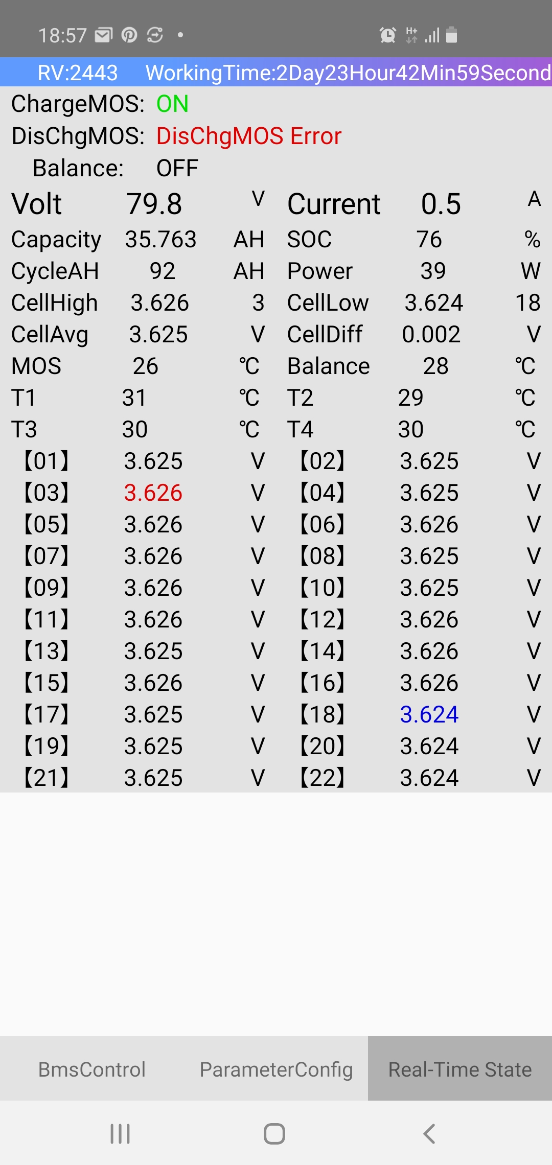
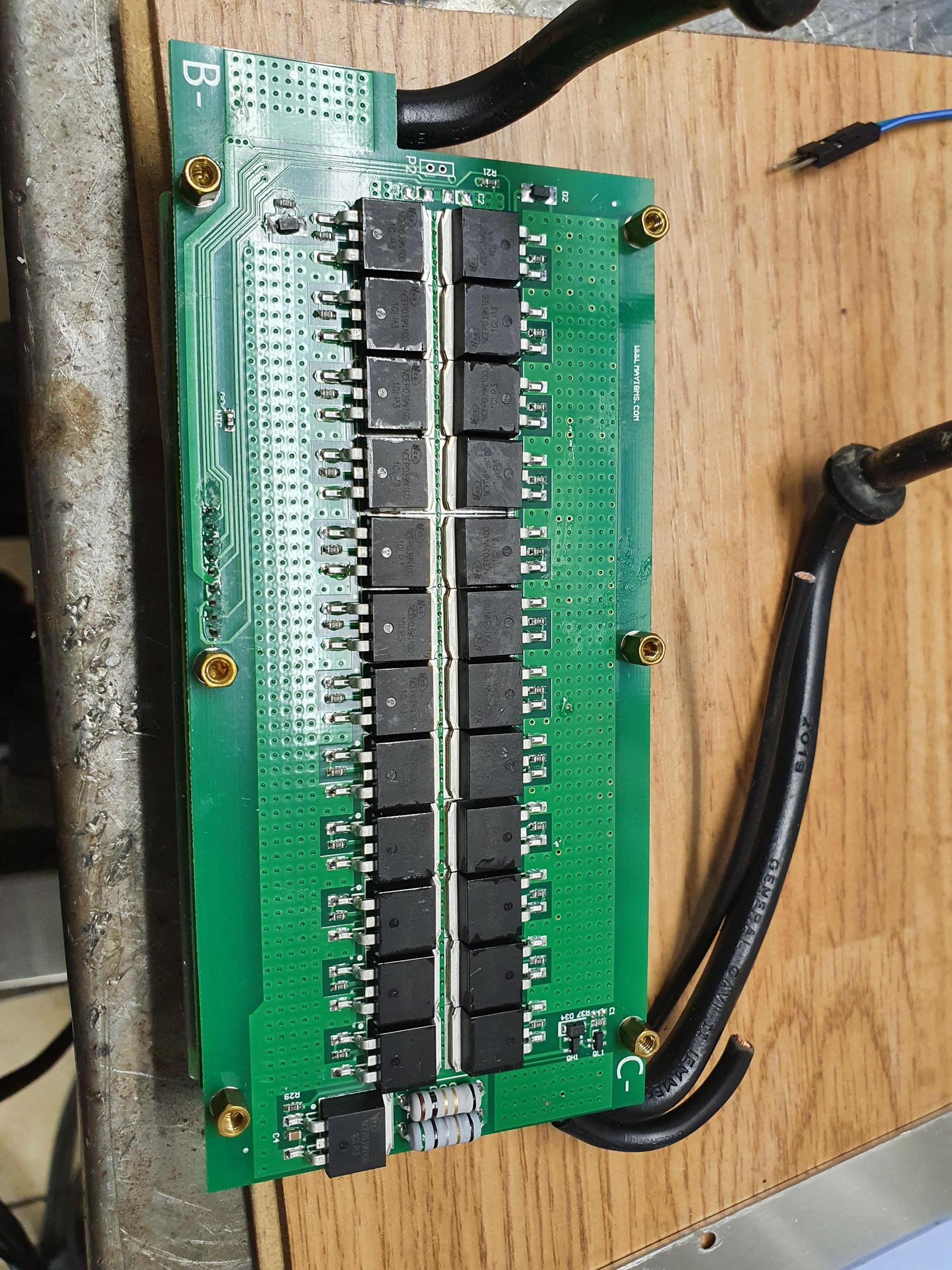
My ant bms broke when I turned it on at last ride:
I took it apart to get a closer look at what is going on.
It looks ok at first glance, but when I measure the discharge fets are shorted.
It looks like all of them are driven from the same source, with just an individual resistor to each mosfet.
I measured to each mosfet, all of them seems ok
")
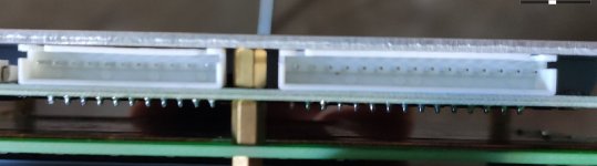
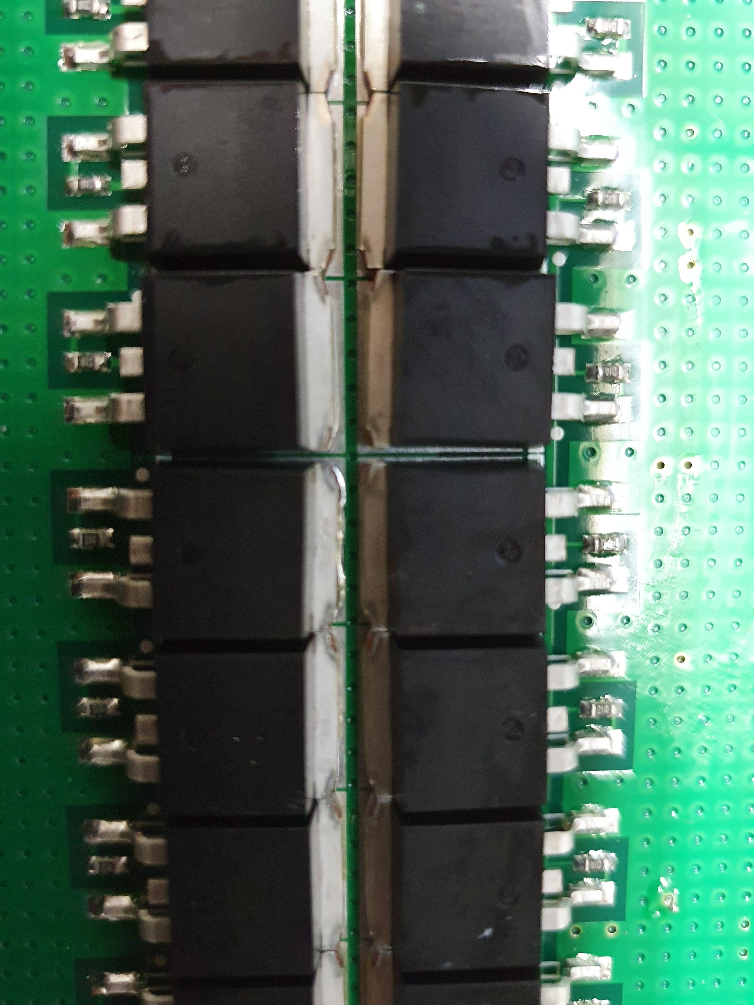
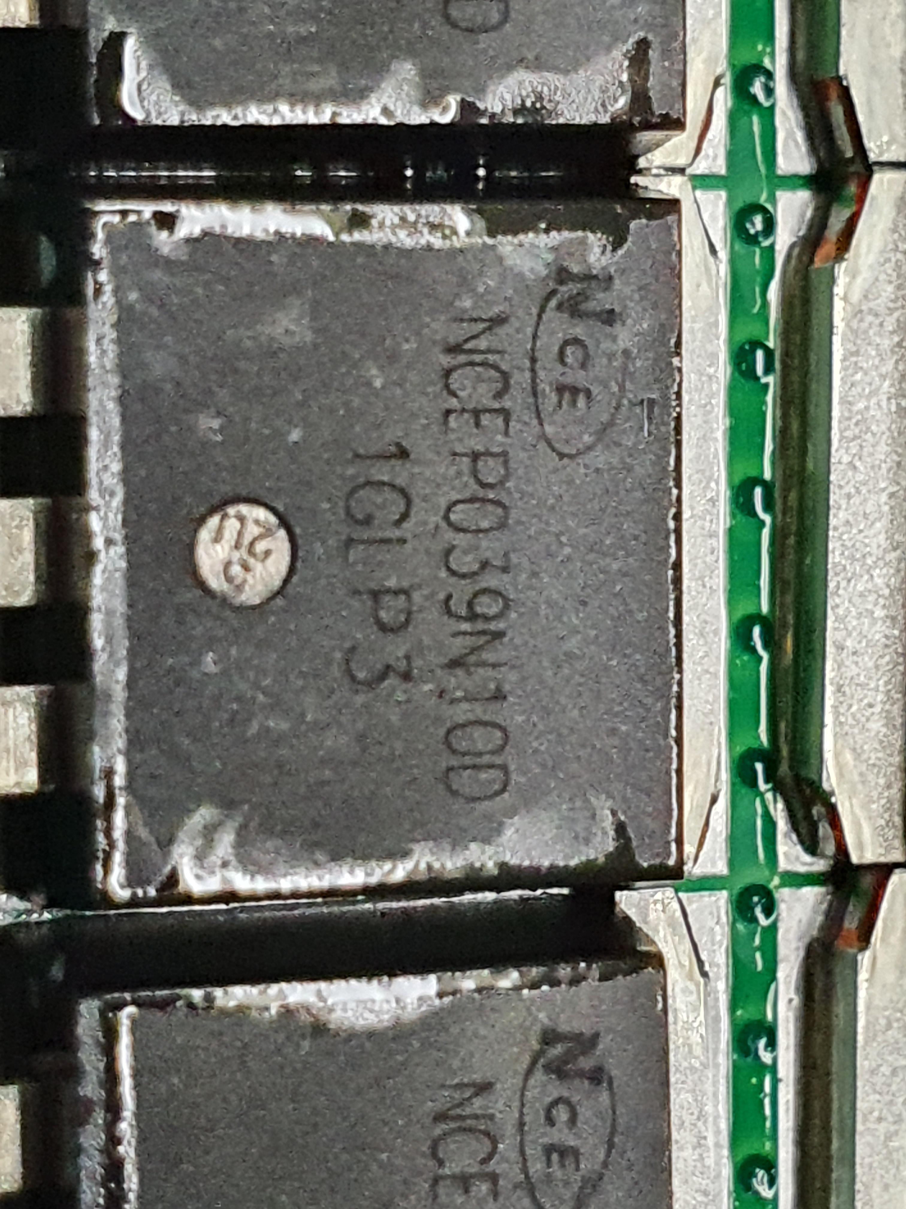
When I took a closer look I think I see the broken one:
The solder on the middle one in the picture seems to have melted.
Both charge and discharge mosfets are the same.
What I would like to do is unsolder all of them, solder on a 1mm copper plate on the board and use that to get P-.
Then solder back 12 discharge mosfets and maybe 6-10 charge mosfets on the copper plate. Then the charge mosfets will only be for charging, all discharging will only be trough the discharge mosfets.
But I am not sure if I can do that without damaging the mosfets?
Would it work to just hold a hot soldering iron to the metal part of the mosfets that sticks out, and lift off the mosfet with pliers when the solder melts?