• Howdy! we're looking for donations to finish custom knowledgebase software for this forum. Please see our Funding drive thread

BMC motor fault finding assistance

RevHead

1 mW
Joined
Dec 12, 2012
Messages
18
Location
Melbourne, Australia
Hello Smart People
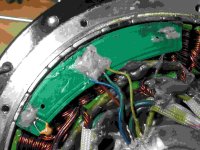
I've been given a BMC motor to fix. Unfortunately the owner who lives far away didn't leave me the controller.
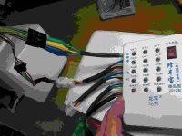
I'm using a Golden Motor external controller help fault find and this is what has happened so far.
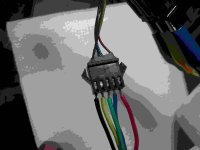
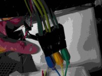
When I connect up the phase wires (without connecting the hall sensor wires) I get some irregular movement of the motor after I help it move manually but the thin wire alligator clips I use to connect yellow and green phase wires to the controller melt. The blue is fine.
I thought this might be because GM have their yellow and green wires arse about. So I swapped them (green to yellow, yellow to green) but the same result occurred.
What could the possible fault be?
If the phase wires were shorting I thought I wouldn't get any movement from the motor.
What do you all think?
 
The bmc probably has shorted wires in the axle tube. If it has a lumpy feeling when you turn the motor it by hand.
 
Thanks Mr Electric.
I'll bite the bullet and open her up and check.
I love this forum, it's my lunchtime reading, I hope that doesn't sound sad. :)
 
One easy check is to measure resistance between the phase wires and the motor axle. There should not be any connection. You could still get movement if only two of the 3 phase wires are shorted.
I assume your controller can run sensorless.
 
RevHead said:
Thanks Mr Electric.
I'll bite the bullet and open her up and check.
I love this forum, it's my lunchtime reading, I hope that doesn't sound sad. :)
you don't need to open it to check for phase wire shorts. if it doesn't run almost freely in both directions (one is freewheel, so it WILL turn freely in one direction) and is hard to turn, then there is a short in the phase wires. ANY two wires shorted will give this effect.
if it stutters at least, and won't turn, then there could be a controller fault (burnt mosfets maybe) or broken hall wires/hall sensors.
 
Right, if you spin the motor in the forward direction, there won't be any resistance due to the freewheel. Spin the wheel backwards and there should be a slight amount of resistance. If resistance is strong, it indicates a short. Do this test with the controller disconnected.
 
hello Peeps once again,
I've been a sick puppy for over a week and have only now returned to this infuriating bmc motor.
Here is the state of play(sic) so far.....
The motor spins smoothly in both directions without a controller connected, the freewheel does as it's supposed to and in the other direction it turns without the lumpy/heavy cogging feel that I recognise from my numerous Golden Motor repairs.
Still when I connect an external controller, I get a small amount of irregular rotation of the wheel then the alligator clips I use to connect the motor to the controller burn out but only the green and yellow ones, not the blue.
I think that the suggestions outlined in the above posts are probably right, ie, some damage to the wires running thru the axle but I would like to give the owner of the wheel a more confident appraisal of the problem.
He's paying me to diagnose the issue so I owe him a better answer than a maybe/dunno/suppose/sorta reply which is all I can give atm.
I've got the side off opposite the disc rotor and can see the insides are looking clean/no dark patches/etc.

Sorry to be a pain but I'm a little out of my depth on this one.
 
It sounds like the motor windings and phase wires are OK then.

Another test is to connect the controller but don't hook up the phase wires, then measure the voltage on each of the 3 hall signal wires as you slowly turn the motor backwards. Each of them should toggle from 0 to 5v as the motor turns.
What's usually the red hall cable wire should be steady 5V.
 
This is where I'm up to.
Some pics showing the data I got from the little doflicky device I got from China on my visit last year.
 

Attachments

  • DSC_0734-1.jpg
    DSC_0734-1.jpg
    90.4 KB · Views: 818
  • DSC_0735-1.jpg
    DSC_0735-1.jpg
    82.4 KB · Views: 818
  • DSC_0736-1.jpg
    DSC_0736-1.jpg
    82 KB · Views: 818
  • DSC_0737-1.jpg
    DSC_0737-1.jpg
    86.3 KB · Views: 818
  • DSC_0741-1.jpg
    DSC_0741-1.jpg
    83.8 KB · Views: 818
Wow, the pictures are sort of messed up, but I can see them.
When posting pictures, it helps to resize them to 800x600 or less first.

The tester is cool, but the instructions are in chinese. If the hall signals are all good, then everything points to a controller problem, but it is not a typical failure mode.


What battery voltage are you using?
 
Sorry about the bad pics. I had to resize them as they were too large for the forum as my phone usually takes them.
I hear what youy are saying about a controller issue but I haven't even got the controller here. I've been using one of our external controllers from our stock which works fine.
We are using 48volts.
Now I have a second failed bmc bought from Cycle9. It was tested before being sent out but it has never worked at this end.
I'll tell you all more as I run some tests
 
I also have 2 bmc from cycle 9 that I bought with knowing they had problems. Philistine and Stevo both had problems similar to what I'm experencing which is phase wires get hot immediately, couple seconds,bike upside down, lyen controller..18 fet 85volts. Fields are good,fets I'm not sure about, and wires have been replaced thru axle. Watching this thread with much intrest. Both these worked with a 350watt front wheel geared motor controller that E-bike-kit sold a couple years ago as a sample kit, (Mckeefer did a big evualtion on this motor) and a sensorless controller wilderness energy I think. Rolled the wheel backwards and hit throttle....there went that controller.
 
One thing I've found is on the older BMC motors, the hall sensors are located in the motor slots. This causes the timing advance to be off and can cause problems with many controllers. They fixed this on the newer ones by relocating the hall sensors. With the right controller, the old setup works. This feature has caused many people problems.

One test is to simply look at the hall sensor placement.

The real test is to put 2-5 amps through a pair of phase wires while looking at the hall signals. With power applied, the rotor will align with the stator strongly in one position. In this position, one of the 3 hall sensors should be right on the trigger point and should be possible to trigger it by slightly moving the rotor back and forth. It should be possble to dial in the hall sensor locations using this method. If the sensors trigger right at the spot where the rotor aligns, it will be neutrally timed, which is what the controller is looking for.

To perform this test you'd need a current limited power supply, like a bench power supply, and the motor would need to be apart. Of course, moving the sensors is not easy either.
 
I would guess you have the wrong controller too. The bmc is a finicky high performance motor. If something is not right it just will not work. A direct drive would be more forgiving.
I always use bmc controllers with bmc motors. Even the crystalite analogue controllers will not work with some bmc motors.
Other possibilities
- Wire colors not properly matched. It will not be color to color on non bmc controllers.
- hall wires grounded to case
- wrong wire termination at phase coils when motor was rewired.
 
I have received some not working 50 amp BMC controllers. Sometimes the female pins just need to be pushed back into place with an exacto blade. I have one tested and ready to ship for $60. You can't buy these anymore as you can see at ebikessf.com. They are being redesigned to accept the CA plug and will be 40 amp. Still waiting for my stock to arrive. I would check those 5 hall pins in the leads from the motor. Make sure they are pushed all the way to the end. Even a half a mm can cause a fault.
 

Attachments

  • 50 amp.jpg
    50 amp.jpg
    122.6 KB · Views: 1,378
I tried the combos that Illia has posted on his site , and others, that work with Lyen controllers , no go. I will check hall continunity again
Mr Electric....what do you mean by wrong wire at phase coils.....when phase wires get changed to any other combo when fiddling with it?
Fetcher just what is the trigger point? Its going past magnets all the time?
The motors are apart. One is sitting in a rear triangle mounted on a piece of plywood.for 3 weeks now grrr
I'm kooking at things right now 9:40 central time sat
 
Revhead....maybe the wires on the testor are bad after you said they were melting. Just a thought.
I bought some clip extensions cords and some were bad right out of the package and especially after a high current episode.
 
Can you post a picture of the hall sensors that shows their position relative to the stator slots?

If power is fed to any pair of phase wires, the rotor will align to a spot. at this spot, one of the sensors should be right at the trigger point.

I had a hard time finding the right wiring combination with my analog Crystalyte controller. The colors don't match. Even then, the best combination still has a higher than normal no load current.
 
The fets are glued about 0.050 behind the right side of the coil front. Don't know how to do pics....embarassing I know.
So far in testing I found the pos trace from the wire to the halls is bad. and the other a bad yellow wire trace.
 
Bad hall wiring can certainly cause problems!

If you look at the 3 hall sensors, are they located in the middle of the slots between windings, or are they offset a little to one side of the slot?
 
cassschr1 said:
They are offset to the left of the slot. About .050 thousandths of pole is showing. Its like this on both motors.

OK, then that is the newer style that "should" work OK with most controllers.

If all 3 hall signals test out OK and you still have issues, I'd suspect the wiring combination between motor and controller.
You may need to go through a trial and error test to find the right one. Instructions are here:
http://endless-sphere.com/forums/viewtopic.php?f=16&t=3484
 
Back
Top