In planning
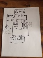
my next build, I'd like to go with this concept of BMS-controlled contactor, so I've drawn up my planned wiring as such for this thread, for others that might be thinking of this route:

In this configuration, current from the battery will bypass the BMS to get to the controller. In the case of undervoltage, excessive voltage drop, or other battery issue, the BMS will cut output to the 120VDC to 12VDC converter, which will then cause the main contactor coil to open and cut power to the controller, thus preventing further damage to the battery during discharge. Charging is still done through the BMS, though, so it still will be able to trigger overcurrent/overvoltage protection.
The main element I'd like to focus on for critiques and comments is that I have the 12v converter wired to the battery's main + and -, via a switch. I can place this switch on the handlebars, but at my planned 28s, I'd rather not put up to 120VDC next to my hands while riding. More likely, I will use a circuit breaker-type cutoff switch in a discrete location, such as under the faux fuel tank, or next to my seat, something easy to reach; and have the contactor be powered on at all times.
My rationale is this: once purchasing the parts, I can test and measure the idle/parasitic no-load draw being used by the DC/DC converter. The DC/DC converter 12V output will be 0v, until switched on by a key, via a relay. If the idle draw is less than 5w, this is acceptable to me; I can put the converter input switch in a hard-to-reach spot and only turn it off if the bike is to be unused for a week or longer. If more than 5W, I should switch the converter's 120v input on every use, and will need to build and place the switch in a convenient (and electrically safe) location accordingly. Essentially, my plan is to have the 12V converter be "on" all the time, and only switch the 12vdc output on and off with each ride.
Let me know your thoughts on how this will work, if there are any suggestions