• Howdy! we're looking for donations to finish custom knowledgebase software for this forum. Please see our Funding drive thread

BMS fisrt connection, cables order question

Joined
Nov 19, 2014
Messages
95
Location
Canada
Hi folks, about BMS, is it necessary to respect a specific order to connect a cables when you connect it for the first time? or do not matter?

Exemple, my batterys pack is ready and I need to solder or connect all cables from the BMS. Wath is the first cables to connect?

Thanks a lot... :bigthumb:
 
It kind of depends on what type of BMS you have. Some have a charge connector some don't.

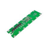
Give us a manufacture and model number and a picture of what you got so we can give you accurate information.

:D :bolt:
 
I believe this to be correct wiring, but wait until it is double-checked by other members.
Also, what company did you purchase this from?
Can you give us a link?

B+ To the positive connector at the beginning of you battery pack.
B- To the negative connector at the end of your battery pack.

P+ To the positive side of the connector to your controller and/or charger.
P- To the negative side of the connector to your controller and/or charger.

B1 Connects in-between cell groups 1 and 2.
B2 Connects in-between cell groups 2 and 3.
B3 Connects in-between cell groups 3 and 4.
B4 Connects in-between cell groups 4 and 5.
B5 Connects in-between cell groups 5 and 6.

Ect. Keep following the above pattern until you finish at cell groups 12 and 13.

:D :bolt:
 
Ok, If I understand, at the beginning, I will connect B+ after B- and followed to B1,B2 etc right?


I don't know the official brand, I bought from Ebay.

https://www.ebay.ca/itm/203636551873?_trkparms=amclksrc%3DITM%26aid%3D111001%26algo%3DREC.SEED%26ao%3D1%26asc%3D20180816085401%26meid%3D461571db813845bd805d560e41338440%26pid%3D100970%26rk%3D1%26rkt%3D15%26sd%3D203636551873%26itm%3D203636551873%26pmt%3D1%26noa%3D1%26pg%3D2380057%26brand%3DUnbranded&_trksid=p2380057.c100970.m5481&_trkparms=pageci%3Aab5f4d2b-b1d6-11ec-b60c-a69bd79bfaa4%7Cparentrq%3Ae5e736cc17f0a9d95ac79592fffbffa6%7Ciid%3A1
 
I recommend:
Attach the B- connection first.
Then attach B1, B2... up to the highest cell
Attach B+ last.

Some models don't care about order. Some may blow up if you attach B+ before the lower cells.
 
Hold everything!!!

Turns out your battery box should only assemble one way. At least according to the eBay picture.

BMS in case.JPG

Looks from here it is already per-configured and can only go one way.

:D :bolt:
 
I finished to build my pack yestherday, This BMS seem to not work properly. When I put the charger, some part (Paralel Cells) not reach 4.2v, stay to 3.8 and 3.9, The fisrt line and the end seem ok,arround 4.2v. I follow the order like fetcher said B1, B2... up to the highest cell
 
s-l500.jpg


Could be defective BMS ... downside of buying kit from ebay with BMS that's no longer avail as stand alone purchase. This JABS 30A BMS would've been worth a try from Aliexpress except same problem as it's no longer available.

Hcf149eb6b8564a7ab53fb6be91e73c5ap.jpg

https://www.aliexpress.com/item/4000276684287.html?gps-id=pcDetailBottomMoreThisSeller&scm=1007.13339.109600.0&scm_id=1007.13339.109600.0&scm-url=1007.13339.109600.0&pvid=73d89710-0d04-4003-a592-ae618f9c568e

Options:
Don't use a BMS ... just an inline 15A or 20A fuse (carry extras) better to under-fuse than over-fuse
https://www.amazon.com/MulWark-Waterproof-Pigtail-Automotive-Motorbikes/dp/B08JZ5C29C/ref=psdc_15729671_t3_B07WMR5XNK

Buy a 30A BMS and wire/solder to your existing Chinese kit
61Bco7IxgkL._AC_SY450_.jpg

https://www.amazon.com/Rechargeable-Lithium-Battery-Electric-Bicycle/dp/B07XR8KDXM?th=1
Amazon is good about a refund or replacement if BMS is defective
 
General_Lee said:
I finished to build my pack yestherday, This BMS seem to not work properly. When I put the charger, some part (Paralel Cells) not reach 4.2v, stay to 3.8 and 3.9, The fisrt line and the end seem ok,arround 4.2v. I follow the order like fetcher said B1, B2... up to the highest cell
As soon as the first cell group reaches 4.2v, the BMS will stop the charging current. It will take a long time for the high cell group(s) to bleed down enough for charging to start again.

You may need to manually charge the low cell groups to bring them up to 4.2v. After that, the balancing function should keep them close. You can also use a resistor or small light bulb to drain the higher groups to make them all equal.

Also, make sure you use heavy wire between the BMS and the B+ and B- connections on the pack. Voltage drop in these wires will artificially raise the voltage on the end cells.
 
What cells did you use? Were they Grade A name brand cells or no name Chinese cells?

Was the voltage variance of the 78 cells within at least 0.03V of each other before assembly? What was the voltage variance of each parallel group after kit assembly before charging ???

Best to use fechter discharging suggestion to bring each of the thirteen 6p groups within at least 0.10V (if not 0.03V) of each other after rest. Then try charging again for an hour at 0.5C rate and check the thirteen 6p group voltages again.

If you have the patience and time "equalize" all thirteen of the 6p groups within 0.01V of each other (after 1hr rest) before charging at 0.5C rate for 1 hr and again checking the thirteen 6p-groups for variance. They should still be witihin 0.02V of each other assuming all the busbar connections are GOOD and the new cells are Grade A.
 
I use Sony Murata VTC6 18650 cells.

My paralel line balanced it was 4.13, 4.03, 4.17, 3.99, 4.14, 4.05, 4.12. Now I charged manualy each line and they have arround 4.60.
I will discharge and charge the pack again. If the result is the same (not good balanced), I will change the BMS like your recommandation.
 
General_Lee said:
I use Sony Murata VTC6 18650 cells.

My paralel line balanced it was 4.13, 4.03, 4.17, 3.99, 4.14, 4.05, 4.12. Now I charged manualy each line and they have arround 4.60.
Why did you charge to 4.60V when 4.20V is MAX with 4.10V even better for prolonging 18650 cycle life longevity? You were fortunate the pack didn't explode ... if you actually charged "each line" to 4.60V :(

Should've instead discharged so all were between 3.99V-4.00V (after 1 hr rest). Then let them rest for 5 days and check again. Hopefully the parallel line voltages would still be within 0.01V of each other or at least within 0.03V of each other with new VTC6 cells that haven't been abused. Do you only have 7 parallel lines (4.13, 4.03, 4.17, 3.99, 4.14, 4.05, 4.12) ?

Charging each of the parallel lines of cells to 4.60V has drastically decreased the usefullness, functionality, effectiveness of your VTC6 pack.
General_Lee said:
My paralel line balanced it was 4.13, 4.03, 4.17, 3.99, 4.14, 4.05, 4.12.
So you only have seven parallel lines (groups)?
General_Lee said:
I will discharge and charge the pack again. If the result is the same (not good balanced), I will change the BMS like your recommandation.
Charging your VTC6 cells to 4.60V has drastically impaired your pack. Getting another BMS won't cure the cells.
 
Big Sorry :( , not 4.60 but 4.16v


Yes, if you check the picture above. you will see 7 point.
I checked the voltage between B+ and B12, B11 and B10 etc.
But I realise now, I maybe not prob correclty.
 
How's it going? This looks to be the ebay kit you purchased ... https://www.ebay.com/itm/203636551873?chn=ps&mkevt=1&mkcid=28&var=504074994238

My guess is that the recommended 18650 cells for using in this kit are ones rated closer to 2500mAh with a 5 amp Maximum Continuous Discharge rating. Your 13S6P 20A kit isn't designed for use with VTC6 cells having a MCD rating of 15amps; ESPECIALLY if the Controller you are using is rated at more than 20amps. The amp rating for determining the correct sized BMS is determined by the amp rating of your Controller (and wattage rating of the Motor). As a general rule the BMS should be rated at least 10amps more than that of the Controllers' amp rating.

Assume you let your pack rest over the past few days? So let us know what's the current voltage readings between the following battery tabs ...

B- to B1 = _.__v
B1 to B2 = _.__v
B2 to B3 = _.__v
B3 to B4 = _.__v
B4 to B5 = _.__v
B5 to B6 = _.__v
B6 to B7 = _.__v
B7 to B8 = _.__v
B8 to B9 = _.__v
B9 to B10 = _.__v
B10 to B11 = _.__v
B11 to B12 = _.__v
B12 to B+ = _.__v

Hopefully, the variance between these 13 parallel lines is no more than 0.10V (100mV). Ideally with brand name new VTC6 cells no more variance than 0.03V (30mV) after your first few discharges and charging again to 53.3V ... 4.10V(avg) x 13.
General_Lee said:
My paralel line balanced it was 4.13, 4.03, 4.17, 3.99, 4.14, 4.05, 4.12.
That's a variance of: 4.17V - 3.99V = 0.18V (180mV) ... too much variance for brand new (fresh) VTC6 cells.

Using fresh new VTC6 cells there shouldn't be that much variance (180mV). IMO the degree of variance that you measured is not due to the BMS. More likely some of the 156 spot-welded cells (neg & positive ends) didn't make GOOD contact with the bus bar strips or some of cells may have been slightly damaged during spot-welding.

Is this your first build using a spot-welder?
What spot-welder did you use?
 
Dear friends
Need help how to understand instruction which came with BMS from Aliexpress:

https://www.aliexpress.com/item/33017576894.html?spm=a2g0o.productlist.0.0.556951feehcmAv&algo_pvid=784682ae-ea26-432a-bdee-ea5d44b1f272&algo_exp_id=784682ae-ea26-432a-bdee-ea5d44b1f272-1&pdp_ext_f=%7B%22sku_id%22%3A%2267180582939%22%7D&pdp_pi=-1%3B14.74%3B-1%3B-1%40salePrice%3BUSD%3Bsearch-mainSearch

Order of connection:
Step1: Connect charging /discharging wire , battery pack negative wire
Step2:After confirm the wires are connected OK, plug the connector cable in the BMS
DO NOT plug CONNECTOR CABLE in the BMS before connect wire!!

Which is CABLE? Which is wire? I think it's time they hire someone who knows how to translate to English!!!
 
Hi Guys, my BMS not working properly, some line rise over 4.2v and when I discharge, some line come below 3.0v. It supposed to stop before or after. You Know!

My pack full charged:
4.185
4.198
4.211
4.198
4.208
4.202
4.198
4.204
4.216
4.197
4.194
4.205
4.195

I will change my BMS for other.

My spot welder is very good, I don't think that is the problem. https://www.ebay.com/itm/194437974113?hash=item2d45680861:g:QjIAAOSwkuxf~UHY
Is not my firt time :roll:

Sorry for my English guys! :( thanks for your helps :mrgreen:
 
.025v difference from weakest to strongest is much of a difference. Looks to me like the bms is working fine.

:D :bolt:
 
General_Lee said:
Hi Guys, my BMS not working properly, some line rise over 4.2v and when I discharge, some line come below 3.0v. It supposed to stop before or after. You Know! ... I will change my BMS for other.
BMSs' at best only balance the parallel lines/groups within 25-30mV of each other. Variance from 4.185V to 4.216V = 31mV with FULL charge is no indication (in and of itself) that your BMS is defective. Your Controller is what determines the Low Voltage Cutoff (LVC) for example 3.20V.

What makes you think your BMS isn't working properly based on these 13 parallel line/group voltage variances ...
General_Lee said:
My pack full charged:
4.185
4.198
4.211
4.198
4.208
4.202
4.198
4.204
4.216
4.197
4.194
4.205
4.195
Most BMSs' only TOP balance the parallel lines/groups within 25-30mV of each other. Generic BMSs' do not BOTTOM balance! In order to do that you'll need an "Active" equalizing (BMS) balance board, but only if the 13 parallel line/group variance is more than 100mV. But that shouldn't be of any concern with "new" 18650 cells ... only as the pack ages to prolong the packs' life ALAP.

For best cycle life LVC no lower than 3.20V instead of 3.00V, and if practical even 3.40V. to prolong cycle life. You'll always get good bounce back voltage (even at 3.0V) after resting at least a couple hours before charging again.
Suspect the reason you chose VT6C was partially for raw performance (MCD) ... rather than casual cruising drawing no more than 20amps. If your Controller has a 30amp rating, than best to use a 40amp BMS.

That battery kit with its thin nickel strips and 20amp BMS is designed for casual use with a 20amp Controller. So why the need for VTC6 cells with a 6P MAX Continuous Discharge rating of 90amps (realistically 10 sec PEAK 90A discharge for cycle life longevity).
 
Back
Top