You are using an out of date browser. It may not display this or other websites correctly.
You should upgrade or use an alternative browser.
You should upgrade or use an alternative browser.
BMS question
- Thread starter Geoffers
- Start date
Do both your BMS and inverter have a control bus that will allow that? It doesn't have to be the same kind of control bus, since you wouldn't be connecting them directly together, but they do both have to have the ability to provide info and / or react to control data.
You'd need an MCU or computer of some kind to receive the data from each, process it however you require, and send the appropriate control signals to each, and then write the code to do this.
You'd need an MCU or computer of some kind to receive the data from each, process it however you require, and send the appropriate control signals to each, and then write the code to do this.
I hope so, the Daly has a unmarked plug that I think is rs485&can and also has the option in the app to set up communication to different inverters. The growatt inverters I have are on this list so  they will talk.
I think it's maybe less important to have a link with li ion Vs li po4 , the voltage range between full soc and flat is much greater on the li ion so inverters can operate fairly accurate from voltage alone.
Please feel free to correct me on this if I'm wrong
I think it's maybe less important to have a link with li ion Vs li po4 , the voltage range between full soc and flat is much greater on the li ion so inverters can operate fairly accurate from voltage alone.
Please feel free to correct me on this if I'm wrong
Another question I have is about temperature sensing, each battery has 4cells and one temperature sensor (ntc I think?)
The BMS has one temperature sensor that sort of dangles down over the batteries.
Does anyone know of a battery temperature monitor I could fit? There's 7 sensors.
I could make my own with a pic but I'm not really looking for another project!
Thanks Geoff
The BMS has one temperature sensor that sort of dangles down over the batteries.
Does anyone know of a battery temperature monitor I could fit? There's 7 sensors.
I could make my own with a pic but I'm not really looking for another project!
Thanks Geoff
There's lots of temperature sensing units out there, most only read one sensor. The ones that read more than one usualy only display one at a time.
But there are many different kinds of actual sensors, and you have to use a sensing unit that can be or is calibrated to that specific sensor. Many things use "10K NTC" thermistors, but there are many versions of them with different curves of resistance vs temperature. Some use digital-output sensors like the DS18x20 (x often being "B") with various output types, protocols, and data formats. Etc.
So if each thing you want to sense temperature of using the existing sensor has a different sensor in it, you'll need different sensing units for each. If they're all the same you only need one kind, at least.
If using analog sensors, like the 10K NTC types, to sense them with an external unit, you'd need to disconnect them from whatever had been reading them before, or they'll interfere with each other. In this event it's "simpler" to use sensing devices that have their own sensors you can install into the monitored devices.
Digital sensors can be read by more than one device on the same line, usually, like the DS18B20. (note that some DS's and others like them are clones/counterfeits, and all have the same address so they can't be used on the same bus).
Thanks,
I've been looking into it a bit and have a feeling there's a little project coming
I'm thinking it might be best to try and trick the BMS a bit. I need to monitor 7 batteries, if any one of them goes high the load needs switching off.
A simple pic with a/d on it could monitor all the batteries and the set a digital potentiometer to the average, if one starts to run away just feed the BMS that temperature via the digi pot then the BMS will always see the hottest battery if there's a problem?
Do you think that would work on?
Is there anything that does that available?
If not I'll have to make it, I can't afford a
Cheers Geoff
I find myself deeper in the mine field!
I'd contacted the seller of the BMS to ask if it could be altered to li ion which they didn't really know.
Now he has come back to me and said this BMS isn't powerful enough for my inverters could I return it for a refund .
My inverters are 5kw each X3 so a 15kw system.
I don't expect to draw much more than a 10kw peak, but each inverter 'can' draw a maximum of 100A at 48 volts.
The BMS is a daly 300A BMS, which I thought could handle 300A peak 150A constant, I'm running quite a few motors on this, the bigger ones are all on inverter drives so fairly soft to start.
Anyone suggest a BMS that would be suitable? I had wondered about using 2 in parallel ?
It will be a bit different to a ev BMS as I also plan for up to 15kw solar input so ideally need 300A either way, I think this makes it difficult for a contactor BMS as charge and discharge port are shared?
Thanks Geoff
Ps I might be glad to change as I was aware the Daly only handle 150A charge current.
eee291
100 kW
You can buy inverter bms from aliexpress or alibaba
Cheers,
I've been in contact with seplos, so am going to end up with 2 BMS and 2 batteries both with 200A charge/discharge capacity.
Also each one has 4 ntc inputs so will properly monitor the temperature.
I already have one running the house battery so am familiar with them too, just one app junking up my phone!
I don't know of anything specifically to do that; there are plenty of analog multiplexers that can be set to cycle thru the inputs or be addressed by an MCU, but haven't seen one that would "know" which input was in a specific state to then latch to that one.I'm thinking it might be best to try and trick the BMS a bit. I need to monitor 7 batteries, if any one of them goes high the load needs switching off.
A simple pic with a/d on it could monitor all the batteries and the set a digital potentiometer to the average, if one starts to run away just feed the BMS that temperature via the digi pot then the BMS will always see the hottest battery if there's a problem?
Do you think that would work on?
Is there anything that does that available?
If not I'll have to make it, I can't afford a
Cheers Geoff
Probably simpler is to use the MCU to read separate sensors (simultaneously or sequentially) than the one the BMS uses, then use whatever switch input the BMS has available to turn it off whenever your chosen limit is exceeded, using an open-collector transistor switch. You can use this method for any sensor, not just temperatures. With the OC transistor you can parallel all the OC's and whichever one is triggered will turn on and short to ground, so if the input to the BMS turns off the BMS when grounded, that directly works. If not, you use the OC's to trigger a relay or other electronic switch to do whatever the BMS input requires.
Many BMS "temperature sensors" are not reading the temperature, they are just NC thermal switches wired to the "on" switch port of the BMS, so they are closed, keeping the BMS on, until they exceed the marked temperature on them, when they open, turnign the BMS off.
You could use a JBD contactor based BMS. Then use a contactor capable of whatever current is required.My inverters are 5kw each X3 so a 15kw system.
I don't expect to draw much more than a 10kw peak, but each inverter 'can' draw a maximum of 100A at 48 volts.
The BMS is a daly 300A BMS, which I thought could handle 300A peak 150A constant, I'm running quite a few motors on this, the bigger ones are all on inverter drives so fairly soft to start.
Anyone suggest a BMS that would be suitable?
They do make at least one that can do 300A. But in case the BMS doesnt' have software to handle the current you need, you could use a shunt with say, half the resistance it's intended to use, which makes it think it is handling half the current that it is. As long as that current only flows thru the shunt and the contactor, not the rest of the BMS, then it doesn't matter how much current you need to handle, as long as those parts and the wiring (and cells) can do it.
Can't safely run them in parallel because if one doesn't turn off the other one takes all the current, bypassing the one that's off and then overloading.I had wondered about using 2 in parallel ?
If you need to pass high current both ways then you probably will have to use a contactor type; all the FET based units I know of use far fewer FETs (or lower capability ones) on the charge port, whether or not they are common or separate C & D ports (because most cells used only handle a small proportion of charge current vs discharge).It will be a bit different to a ev BMS as I also plan for up to 15kw solar input so ideally need 300A either way, I think this makes it difficult for a contactor BMS as charge and discharge port are shared?
You could hack a FET based unit to use more FETs or to drive a contactor instead of FETs, but it's easier to just start with one that does this.
Thanks,
That's interesting , I've been in touch with seplos and suggested using 2x 200A BMS to supply my possible 300A load and they said that's fine?
I'll push them on it before I hand over any money, make sure something hasn't gone adrift in translation! The one I'm looking at passes 200A either way.
They also have a rs485 link between them so if one faults out I guess the other will shut down.
It gets more difficult, they are saying 17days minimum but I've heard this sort of thing before, I'm getting really tight for time now, is anyone aware of UK dealers for jbd or seplos?
Fogstar only seem to have lifep04 BMS
Thanks Geoff
Fogstar only seem to have lifep04 BMS
Thanks Geoff
As long as their BMS's do some form of built-in interlinking to automatically work as a set (without any form of user setup, etc, just built in to do this from the factory) then they can be used that way, but I've not worked with any that can do that yet. If they require the user to set them up to do this, then I wouldn't rely on it to be that way unless their manuals are VERY clear on exactly how to do it, how it works, and what conditions it works under for each available setting in there.
I ran across another contactor-based BMS that says up to 500A
didn't go thru all the specs, and don't think I've ever seen them before, but one more option for you..
didn't go thru all the specs, and don't think I've ever seen them before, but one more option for you..
Thank you, that's another to consider,
Apart from the parameter settings are there likely to be hardware differences between li ion BMS and lifepo4? I've noticed some are for both and some only specify one? I can get a jbd contactor bms from UK tomorrow but it says lifepo4 but the retailer only sells lifepo4 batteries. I'm probably going to order it ? The Daly I had was no trouble to alter parameters to li ion settings.
Thanks Geoff
If the BMS is MCU-based, then the hardware in them is probably identical, and it's just the MCU that's programmed to respond to different voltage levels of the cells. That doesn't mean that the company designed it to be reprogrammable by the user for which chemistry/voltage, so it probably doesn't matter that it physically could be--that's something you have to verify beforehand from the company that makes them: Only if the company has firmware available to the end user for all versions of it, along with the procedure and software (and cabling if required) to reprogram it, or there is a user setting in the user-side software to change chemistry, does it matter. Almost certainly any controller with user-alterable settings or any form of communication to/from the BMS is MCU-based.
If the BMS is "hardware" based, then it uses specific-chemistry (voltage) sensing and detection chips or even discrete components (comparators) that only work correctly with the cell type(s) it was designed for. These are getting rare outside the really cheap stuff for lower currents, but you can only tell for sure by looking up the chip / part numbers on the stuff connected to the cell sense lines.
If the BMS is "hardware" based, then it uses specific-chemistry (voltage) sensing and detection chips or even discrete components (comparators) that only work correctly with the cell type(s) it was designed for. These are getting rare outside the really cheap stuff for lower currents, but you can only tell for sure by looking up the chip / part numbers on the stuff connected to the cell sense lines.


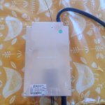
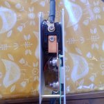
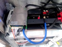
It's arrived!
I've ordered a 500A contactor that can break 2000A at I think 900v so should be up to the job, looks like should be quite easy to bypass the contactor on board give me a more heavy duty setup.
Got me thinking I could use some relays on the contactor coil line to give me a way of building in a few fail safes. Emergency stop button for one, battery over temperature as this bms only has sensors for 2 batteries.
How much current can I push into these batteries CATL li ion 190aH (2.8345kwh/3.7v/4s) 2x 14s which gives me 380aH total.
My chargers can top out at 300A (solar/generator) but there will always be a load , I'm stood by it charging for first time at 120A and a bit nervous! Everything is nice and cool
At the moment I have charge voltage at 58v (4.14) is this about right or should i drop it.
Protection at 4.2v
Discharge protection at 3v.
Am I near right?
Thanks Geoff
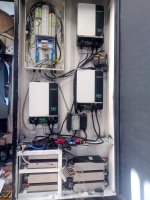
Your ideas look good.View attachment 343848View attachment 343847View attachment 343845View attachment 343846
It's arrived!
I've ordered a 500A contactor that can break 2000A at I think 900v so should be up to the job, looks like should be quite easy to bypass the contactor on board give me a more heavy duty setup.
Got me thinking I could use some relays on the contactor coil line to give me a way of building in a few fail safes. Emergency stop button for one, battery over temperature as this bms only has sensors for 2 batteries.
How much current can I push into these batteries CATL li ion 190aH (2.8345kwh/3.7v/4s) 2x 14s which gives me 380aH total.
My chargers can top out at 300A (solar/generator) but there will always be a load , I'm stood by it charging for first time at 120A and a bit nervous! Everything is nice and cool.
At the moment I have charge voltage at 58v (4.14) is this about right or should i drop it.
Protection at 4.2v
Discharge protection at 3v.
Am I near right?
Thanks Geoff
If it is possible, do you think you could measure how much current is used by the contactor to stay closed? A contactor-based BMS is great for high-power ebike applications, but I haven't considered them for stationary long-term use applications, because I'm always thinking about the constant power draw required to keep the contactor coil activated. Looking forward to seeing your experiences.
I'll try in a mo, think I can get clamp amp on it with out taking it apart?
I see what you mean about coil powered all the time but compared to the load that will be running it's fairly insignificant.
On a normal domestic off grid setup it would be more of a consideration!
I see what you mean about coil powered all the time but compared to the load that will be running it's fairly insignificant.
On a normal domestic off grid setup it would be more of a consideration!
eee291
100 kW
It should only be 2-4 watts, if it's done correctly.because I'm always thinking about the constant power draw required to keep the contactor coil activated
eee291
100 kW
Considering that they came from a car I would say at least 1C or 380A. You can probably charge with higher currents. The limiting factor would be heat, inside the EV they were most likely water cooled.How much current can I push into these batteries CATL li ion 190aH (2.8345kwh/3.7v/4s) 2x 14s which gives me 380aH total.
Your right it's a greedy sod ! 1.4A @ 13v 18.2w!!!
The one I've ordered is made by TE , 12v x 0.13A 1.56w which sounds more like it.
At least it will swap right in as the coil voltage matches.
I was hoping you'd say 1C, in reality my setup will never go above 0.75 C but I'm still nervous!
The one I've ordered is made by TE , 12v x 0.13A 1.56w which sounds more like it.
At least it will swap right in as the coil voltage matches.
I was hoping you'd say 1C, in reality my setup will never go above 0.75 C but I'm still nervous!
Similar threads
- Replies
- 16
- Views
- 3,174
- Replies
- 0
- Views
- 1,293
- Replies
- 58
- Views
- 33,207
- Replies
- 21
- Views
- 4,818
- Replies
- 406
- Views
- 52,748

