
Hi guys
Im hoping to get some help for wiring my first diy bms to my LG pouch cells.
I have 18 cells of long LG pouch type like this..but not these exact ones. However the dimensions are the same.
https://m.dhgate.com/product/ev-battery-high-capacity-3-6v-60ah-prismatic/472469652.html#redirect_detail=PC2WAP
Because of their length, I had to mount them separately in different areas of the bike (inside the frame and on the rear rack)
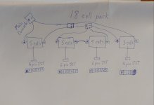
I can not physically connected all 18cells together as it wont fit my application, so splitting the cells up is my only option.
The 2 packs in the center of the photo below were able to be connected with short wiring and those 10 cells are in the same bag.
Also since I wasnt using a bms, i just connected separate JST plugs for each pack to monitor the cells
Since each pack has its own main positive and negative connector, i had to make 3 way connectors to connect packs to each other to increase the voltage.
Ive recently purchased a bms so Id like to wire it up.
Since I have 4 JST plugs already connected, could I just run the bms balance JST wires to those? If its possible then i need to wire them in the correct order correct? Id have to be careful.
I have the main wiring from the bms wired up..just need to focus on the balance wires.
Any tips will be greatly appreciated! Thanks!!
Im hoping to get some help for wiring my first diy bms to my LG pouch cells.
I have 18 cells of long LG pouch type like this..but not these exact ones. However the dimensions are the same.
https://m.dhgate.com/product/ev-battery-high-capacity-3-6v-60ah-prismatic/472469652.html#redirect_detail=PC2WAP
Because of their length, I had to mount them separately in different areas of the bike (inside the frame and on the rear rack)
I can not physically connected all 18cells together as it wont fit my application, so splitting the cells up is my only option.
The 2 packs in the center of the photo below were able to be connected with short wiring and those 10 cells are in the same bag.
Also since I wasnt using a bms, i just connected separate JST plugs for each pack to monitor the cells
Since each pack has its own main positive and negative connector, i had to make 3 way connectors to connect packs to each other to increase the voltage.
Ive recently purchased a bms so Id like to wire it up.
Since I have 4 JST plugs already connected, could I just run the bms balance JST wires to those? If its possible then i need to wire them in the correct order correct? Id have to be careful.
I have the main wiring from the bms wired up..just need to focus on the balance wires.
Any tips will be greatly appreciated! Thanks!!
")