Bonanza "Bulldozer" Dual PhaseRunner AWD

Some DB connectors are rated to 5A per pin, but I don't pan to use even 9 amps with this setup. There is one more pin that could be used on each, I chose to leave it blank at this time. It is easy to put a wire between three pins and solder it, the fourth is a bit far away for that. I would derate the pins to 2 amps max per pin for continuous use. So 6 amps max per 3 pins.

How much charge current do you plan to use?

I'm planning this as an interim solution. Later I'll do a bulk charger and at some point also monitor the cells. Right now I basically can't recharge the bike, it is just impractical. Need to fix that soon.

The charger I'm planning to use first is an Accucel 8150 so it will do 6 amps at 25 volts. Thus far I've been running it at 2 amps because the power supply that was convenient is 60 watts continuous max. I'll probably run it at 5 amps just to leave some margin.

It all depends how much of a hurry you are in. For bulk charging I may set up a pair of 36V meanwells in series at 75V. That would do up to 9 amps. That would charge an empty pack in a bit over one hour. Rarely do I need that.
 
Charging Cable

Here is the first charging cable that will be mounted on the battery pack. The lipo balance connectors go in the pc board. The heavier wires go to the discharge wires for the charge current. A corresponding cable will be made for the charger. A single 6S charger will charge each of the three banks in this battery in turn. Only the one DB15 plug will be required for the charger to battery connection as it carries both the balancing leads and the charging leads.

DSC_5316.JPG
 
Could you use three products like this and a bulk charger to create a two wire charge/balance set up.
http://www.hobbyking.com/hobbyking/store/uh_viewItem.asp?idProduct=7443
 
Hi Alan,
Alan B said:
Some DB connectors are rated to 5A per pin, but I don't pan to use even 9 amps with this setup. There is one more pin that could be used on each, I chose to leave it blank at this time. It is easy to put a wire between three pins and solder it, the fourth is a bit far away for that. I would derate the pins to 2 amps max per pin for continuous use. So 6 amps max per 3 pins.

How much charge current do you plan to use?

I'm planning this as an interim solution. Later I'll do a bulk charger and at some point also monitor the cells. Right now I basically can't recharge the bike, it is just impractical. Need to fix that soon.

The charger I'm planning to use first is an Accucel 8150 so it will do 6 amps at 25 volts. Thus far I've been running it at 2 amps because the power supply that was convenient is 60 watts continuous max. I'll probably run it at 5 amps just to leave some margin.

It all depends how much of a hurry you are in. For bulk charging I may set up a pair of 36V meanwells in series at 75V. That would do up to 9 amps. That would charge an empty pack in a bit over one hour. Rarely do I need that.
Almost identical setup to how I plan! I have 2x Accucel 8150, each will run off a bank of 5x12V7Ah SLAs "acquired" (second hand - they came from UPS's and were slightly under-spec). I didn't quite know what you were planning as far as the charger went, 'tis all. You can always bulk charge through the main leads to the controller if you so desire.

mr.electric said:
Could you use three products like this and a bulk charger to create a two wire charge/balance set up.
http://www.hobbyking.com/hobbyking/store/uh_viewItem.asp?idProduct=7443
These are similar in concept to the Accucel 8150 (different configuration though), but by the reviews, aren't as good. Thanks for the effort though :wink:

Cheers,
GT
 
mr.electric said:
Could you use three products like this and a bulk charger to create a two wire charge/balance set up.
http://www.hobbyking.com/hobbyking/store/uh_viewItem.asp?idProduct=7443

Interesting idea, not sure if it would work. You'd have to connect the inputs in series to the bulk charger. When one switched off while the other two were still charging it would see the whole bulk voltage. Probably would let the smoke out.
 
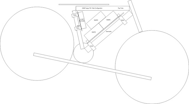
Looking at PaulD's bike from the race got me wondering again about mounting a battery low center. Not sure how to attach it to the bike, but could fit 6x 6S 5AH Lipo down there, which would double the battery capacity of the bike. If I also added another 3 batteries to the triangle (tight) that would give me 15 + 10 amp hours or about 1.8 KWH. That is 70 miles at 25 watt hours per mile, or 50 miles at 35 wh/mi. Long range for weekend rides, or to avoid charging at work.
 
Side View Mirror

Some time ago I selected a mirror for this bike project. This is an important safety item. It has been working well so I will report on it:

Mirrycle MTB Bar End Mountain Bicycle Mirror

DSC_5286.JPG


This mirror grips the inside of the handlebar tube and it fits very well in my handlebars. The hex bolt at the end tightens it in the bars. It is very adjustable and has a good sized convex mirror on the end, approximately 2.5 inches in diameter. This mirror does not seem to suffer from vibration and it provides a good field of view.

Note that installing both shifters on the left grip did not work well. Skip that experiment!

When I upgraded to the Magura throttle I installed the grip on the left hand bar. This grip closes off the handlebar so I drilled a hole in the grip with a large twist drill bit using a battery powered drill on a low speed. The soft plastic material drilled very nicely and made a clean hole.

Here it is on the Magura grip on the left:

DSC_5340.JPG


When you are parking the bicycle the mirror can be folded in so it is over the grip, reducing the overall width to just that of the handlebar.
 
Charging Cabling Change

I've been working on the Charging cables and connectors and I'm not really satisfied with my present plan. The DB-15s are workable but not all that easy and factory made cables are not adequate for the higher charge currents even though the connector pins would be.

So I'm going to try something else. I want a readily available cable/connector setup for 6S that will handle 10 amps. I was not planning to use 10 amps, but I have a pair of excellent chargers that are 10 amp capable, so the wiring should be also. After considering a number of alternatives I decided to try going to 2 connectors rather than one. The primary reason to use one connector is to avoid mistakes that blow things up, but if I constrain the two connectors to be tied together it will have pretty much the same effect. And I can reduce the labor of setting this up A GREAT DEAL. That's my primary motivation - to make this simpler so it will be completed, and to use more reliable cabling.

So the two connectors that are well suited to this, and I already have tools for, are PowerPoles and RJ-45's. The PowerPoles can handle the 10 amp charge current easily, and the RJ can handle the balance connections using standard off the shelf network cable jumpers.

I will make some circuit boards to facilitate this later, but right now I will use my existing PC boards. I have some premade (eBay) 6S JST-XH extensions that I will repurpose (clip off the male connector) and punch into Leviton Quickport RJ-45 jacks and then plug into the JST-XH's on both ends. A short RJ-45 network cable will complete the connection. To this cable I will tie-wrap a red/black wire pair adequate for 10 amps with banana on one end to fit the charger, and 25A PowerPoles on the other to be adjacent to the RJ-45. The bike will have three of these RJ/PowerPole jack sets, and they will be located apart sufficiently that the tie-wrapped cable pair will not be able to reach more than one connector set at a time. So without cutting tie wraps it will not be easy to connect up incorrectly.

I will still have to connect three times to charge (for now), but I will have the option of using a 10 amp 6S charger which will speed things up considerably and make this more practical.

Anyone else interested in using this same setup? I will standardize on pinout and publish it in case anyone else wants to do the same:

RJ45 pin - balance voltage (assumes nom 4V/cell)
1 - 0v
2 - 4v
3 - 8v
4- 12v
5 - 16v
6 - 20v
7 - 24v
8 - nc

JST - XH pin numbers are the same as RJ pin numbers in this design (keeping it simple...)

Later I may make a couple of PC boards to facilitate this technique and make it more durable.

Comments? Better ideas???
 
I have assembled one JST-XH to RJ45 adapter. These punch down RJ's are designed for CAT5E wire, which is thinner than the stranded wire on the eBay JST-XH extensions. So it makes it a bit difficult to punch them down, and it is unclear if it will work reliably in the long term. A PC Board would of course fix this, but that takes time so I want this to work for now. I'll put another adapter together and use it to charge a battery. The continuous monitoring through the RJ cable should give it a good test.

Putting a too small wire in a punch down is not reliable, but putting larger in may work out okay. It is an experiment, at this stage.
 
Completed the second RJ45 jack to JST-XH female adapter and the three charging current cables for the battery pack (one for each 6S block) and installed them on the series/paralleling terminal strip. I checked the output of the cable adapters with the CellLog and it was good. The first 25V 10AH 6S2P section is charging now. Seems to be working! Still to go is to make the other 2 balance to RJ adapters and test them. Then they all need to be mounted semi-permanently on the pack, mount them back on the bike and finish up the charging!!! Not tonite.

I positioned a 12V power supply at work today. An old Astron RS20A which can do 16 amps continuous. Heavy iron. I will probably get a pair of Meanwell 350 watt 15 volt supplies to run the chargers later on, but this is something that was on hand and not being used. It will be adequate for a bit over 200 watts. The Turnigy 8150 charger is 150 watt max so that is enough for it. The Cellpro 10S needs about 325 watts at 15 volts to produce 10A on 6S so the larger Meanwell will be required if I want to charge that fast.

Right now I'm charging the lipo at 2 amps just to be a bit safer, and because the old Astron RS7 I'm using is only good for 5 amps or about 60 watts at 13.8 volts. I have a better supply to use so I can ramp that up when I need to and at least get to 150 watts. The Cellpro's are going to require some different battery cabling (on the charger end) so I'll leave that for later.

One interesting feature of the Cellpro 10S charger is that it can measure internal cell resistance. I have not tested that yet but it may be useful.

I have most of the PC board layout done for an RJ45 to JST-XH paralleling board. Have to sort out the selection of the RJ jack, there are a dizzying number of those jacks on the market and they don't all have the same footprint.
 
The charging process using the new cabling went almost smoothly. It stopped at 5.5AH due to that's what I had set the charger limit. Need to readjust that. Took 6.75 amp hours total after a second cycle to finish. Have to doublecheck the Cycle Analyst when I get power back on the bike, seems like the shunt calibration is a bit off as it was reading a bit more. If so my 72V readings may have been a little higher than they should be, both amp hours and watts.

At this point I think the punch type RJ connectors are going to work. They would work much better if the right wire size was used, they are hard to punch and are stressed with the slightly too large wire.

Voltage Scalable Battery Wiring

When I was working on my pack the other day I realized that if each parallel battery block had a 2 position terminal block the wiring would be more manageable, and it would scale to different voltages more easily. The present setup with a single quad terminal block works well but is specific to three batteries in series, and it brings all the wiring into one spot which increases congestion. Combining a two terminal block and the circuit board for paralleling the balance jacks would be a better modular design. Two modules would make a 48V pack, three for 72V and four for 100V when used with 6S batteries. 5S batteries would work fine as well with correspondingly lower voltage.
 
Battery Charging Wiring Progress

Built three battery bank adapters for charging, and the adapter for the charger. One of the three is not working, for some reason it popped two traces on the adapter board. The other two tested okay into the celllog.

Not sure why the third one popped two traces. They did not pop between the batteries, but on the way to the RJ connector. That implies a temporary short in the RJ, or the caps in the charger took too much to charge up.

Perhaps when I do the final boards I will make the traces a bit heavier, still lighter than the wires to the battery as I would rather pop traces than wires to the lipo batteries!

Also reprogrammed the charger for 10.5 amp hours. Last time it quit too early. It is now charging bank #2. Bank #1 was charged the other day. Bank #3 needs charging also.
 
Thinking further on the blown traces, I suspect the RJ45 connector is a poor choice for this application. Even a tiny momentary short in this application will flow a lot of current through the balance wiring. The RJ connectors don't have enough separation and isolation between the conductors. So for the final implementation I will choose a different connector. Wonder what it should be...

The RJ connectors (used for phone and network) are fine as long as a momentary short is acceptable in the circuit, but there is just too much current available in this balance tap application for that.
 
gtadmin said:
Sorry to hear that Alan. I thought that soldered connections were always better?

I don't think there is a problem with the punch-down connections. They are stressed due to the wire being too large. It is possible that the stress is creating an intermittent short inside the connector somewhere I can't see, however. The female RJ connectors have a pretty large opening, and the pins are easily shorted if a conductive object comes into contact. In retrospect, it is a poor choice for this application.

Let's review what happened. I built up three balance paralleling PC boards and three JST-XH to RJ45 adapters using the Leviton punch down connectors and eBay extension cables. I plugged these into the boards and tested them. The test was a new RJ45 network cable 3 feet long, into a fourth punch down RJ to JST-XH cable. Into this the CellLog was inserted. One balance plug from one battery was plugged into the PCB and the CellLog indicated cell voltages. This was done on all three boards. Then the three balance boards and RJ45 connectors were epoxied to pieces of the red oak to provide a mounting platform. These were mounted on the battery with double stick tape and a large tie wrap for two of them. The third was not mounted yet since it will be over the bike mounting hardware. Then the batteries were plugged into the series/parallel harness and the balance boards. The test with the CellLog was repeated. It indicated a problem. Further investigation revealed two traces on the board had popped (a total non-event, by the way, as opposed to the usual KFF excitement, as these traces pop at low current). These were between the RJ and the first socket, so the overcurrent was not between batteries, but toward the RJ connector.

So at this juncture I have a couple of choices. One is to repair the board and proceed with the RJ for the moment. That would be the least effort path. The other is to rip it apart and change to DB9's for the balance pins and leave the PowerPoles for the charge current. I have DB9 cables available to use so this is possible but a larger effort than repairing or replacing the RJ board. Not sure I have time to do this right now, however, with some other projects that need my attention as well.

The second bank of 10AH 6S Lipo charged last night. Took 6.8AH. so now the pack is 2/3 charged, and the updated settings on the Accucel 8150 charger worked fine. The bank that is not charged is the one with the bad balance/RJ board.
 
Next Steps

I'm going to give the RJ45 one more chance. I'll repair it and see if it holds.

After work I made a quick PCB design for the DB9 design (it uses the PowerPole for charge current and the DB9 for balance wiring). The ExpressPCB system has one board size that they do quick and low cost (3.8 by 2.5 inches), so if your design fits this size you get three boards in a week for about 65 bucks. This battery board is less than half that standard size, so I can put a battery interface board, and a charger interface board on one PCB and cut them apart here. Three is just the right number for now. Their library had both the male and female DB9 connectors, plus a connector that is close to the JST-XH, so I did not have to make a pad layout. That, and being familiar with the software, it took me about an hour to make both layouts. So if I send this in for manufacture this weekend I will probably have boards about the end of the week. If I order parts this weekend they will likely also be here. So I may just do that, especially if I have any more RJ connector problems.
 
Some Success

Built up another PCB as repairing the trace under the solder mask and epoxy was not going to be easy. Installed it on the pack and connected the charger. It passed the charger's cell voltage test and is charging now. If the cycle completes properly the whole pack will be charged. There is a little more work to mount this last charging jack as it sits over the battery mounting hardware, and then reinstall the pack on the bike.

Mounting this PCB to the wood was done with hot melt glue. Probably more appropriate than using the epoxy - easier to do and remove. Though on a really hot day it might get soft, so the long term solution will not use hot glue. Probably not wood either. I am looking at using some aluminum and making the battery much easier to take off.

Matching Tires

Right now I have the Marathon Plus tire on the front and the Big Apple on the back. Should I go ahead and put the other Big Apple on the front, or does it matter??
 
Hi Alan, I can't give you advice as you have more experience in this than me, but my opinion (FWIW) is that the DB9 design "feels" the better choice. I'm going to Adelaide towards the end of the week so I'll be able to get to a component shop and sniff around for ideas. At the moment, I'm leaning towards a DB25 taking all the balance wires out separately; PowerPoles (probably as I have ship loads of them) or similar for the bulk charge leads.

Oh, you posted already! Tyres: I don't think it matters, but I have the Big Apples on both wheels, but then the frame is rigid.

Cheers,
GT
 
gtadmin said:
Hi Alan, I can't give you advice as you have more experience in this than me, but my opinion (FWIW) is that the DB9 design "feels" the better choice. I'm going to Adelaide towards the end of the week so I'll be able to get to a component shop and sniff around for ideas. At the moment, I'm leaning towards a DB25 taking all the balance wires out separately; PowerPoles (probably as I have ship loads of them) or similar for the bulk charge leads.

...

I have considered the DB25, and would do that if I had an 18S charger. What is your plan with the DB25??

I agree that the DB female connectors are a lot more protective for these balance leads.
 
DB9 Charger Interface Boards

This is the mechanical view of the boards I designed tonite. They use a DB9 extension cable to carry balance signals from each battery bank to the charger, and a PowerPole to carry the charging current to each bank. It is set up for 6S banks but could be used for 5S as well.

lipoifc-db9-jstxh-v1.jpg


There are two designs on this board, to be cut apart. This makes more efficient use of the standard low priced fixed board size.

The left half "board" is the battery interface for 6S2P to female DB9. The four holes on the left side are to tie wrap the battery side of the charging cable with a PowerPole right next to the DB9. The two rows of pads are for two JST-XH connectors for the battery balance connectors to plug in.

The right half is the charger interface for 6S. It converts the DB9 male PCB mount jack to a row of pads. I have not found JST-XH cables with female connectors on both ends, the available ones are either bare wires one end or extensions. Either can be used here, just cut off the un-needed connector if there is one and terminate the wires to the pads on the board. The JST-XH female end goes to the charger. The four holes below the row of pads are to tie wrap the wires to the board for support. The other four holes are for tie-wrapping the charging cable to this board as it goes by to the charger. This is just to mechanically tie the two cables together.

The key thing here is to tie the charger cables together at the battery end (or all along the cable's length). We don't want it to be easy to connect the charge cables to one battery group and the balance leads to another. The proper sequence is to connect the cabling to the charger, connect the charge PowerPole to one battery group (parallel batteries) and then connect the balance DB9 plug to the same group. Charge, then disconnect the DB9 and then the PowerPole and repeat with the other battery groups.

In this manner I will charge my 18S pack with a 6S connection on each of three battery groups.
 
My setup is 4x 3S3P packs for the 12S3P motive battery, and a 3S2P pack for the lights etc. The plan is to parallel all balance leads per 3S pack, so that will be 5 lots of 4 wires going to the single DB25 allowing me balance charge each 3S pack separately, or as 2x 6S + 1x 3S. The balancing charge should be only once or twice a month based on how my 8S2P pack for the Aprilia is performing.

With a Meanwell set to 49.2V (4.10 per cell), I will be able to bulk charge the motive pack as a unit monitoring the cell voltages through the balance leads to 2x CellLog8s.

Once it's set up, there is no opportunity to mismatch wires as described by you. Well, that's the plan at the moment unless you see a problem or I find something next week that provides a better alternative.
 
gtadmin said:
My setup is 4x 3S3P packs for the 12S3P motive battery, and a 3S2P pack for the lights etc. The plan is to parallel all balance leads per 3S pack, so that will be 5 lots of 4 wires going to the single DB25 allowing me balance charge each 3S pack separately, or as 2x 6S + 1x 3S. The balancing charge should be only once or twice a month based on how my 8S2P pack for the Aprilia is performing.

With a Meanwell set to 49.2V (4.10 per cell), I will be able to bulk charge the motive pack as a unit monitoring the cell voltages through the balance leads to 2x CellLog8s.

Once it's set up, there is no opportunity to mismatch wires as described by you. Well, that's the plan at the moment unless you see a problem or I find something next week that provides a better alternative.

So effectively the DB25 will bring everything off the bike and then you will have a separate switchyard to select what the charger is connected to. Should work fine. Moves the connectors and issues away from the bike. Makes for more connectors in series. Might be some opportunity for problems in the switchyard depending on how it is wired. You will need to bring the charging wires from the packs separately and that is where the risk lies - keeping the charging and balancing wires safely grouped. Plugging the charger into one charge line and a different balancing group which is at a different potential in the series can blow the charger.
 
Alan B said:
...Might be some opportunity for problems in the switchyard depending on how it is wired. You will need to bring the charging wires from the packs separately and that is where the risk lies - keeping the charging and balancing wires safely grouped. Plugging the charger into one charge line and a different balancing group which is at a different potential in the series can blow the charger.
With common-sense layout, the risk will reduce to close to zero and will be a non-issue. And you only have to do it once (but I'm going to be reaaal careful wiring it :) and test, test and test) The balance wires (from the battery) will plug into JST-XH connectors soldered onto a prototyping board and thence to the DB25. I have found an on-line Aussie supplier for the JST-XH ($6.90 for 10) with free mail 8)

I also have some 10x3 copper strip to use as busbars for paralleling the battery discharge leads, soldering some 4mm connectors onto it so the discharge leads just plug in, then a jumper from one bar to the next to series the batteries.

Just gotta do it now!
 
Sounds good. Hopefully my setup will be working this weekend.

There is a ride near my house that loops around two lakes, about 20 miles. Very popular with the bike crowd. Hopefully I can do that one today if the weather holds. Tomorrow there is an ebike run over to Slacker's Peak in Marin that would be fun to do. Again, the weather is questionable. I don't have a cover for this electronics package yet so am not really ready for wet riding, nor do I have raingear. Maybe a black garbage bag and duct tape, but I hate to resort to that.

I have an old hiking type GPS with a handlebar mount that might be fun to put on the bike. Probably should look at a newer model. Or perhaps a handlebar mount for my Droid...

Another thing that would be fun to set up is Ham Radio APRS that sends GPS position reports. I suppose the Droid can do that too. Amazing how many of these current trendy tech things were invented years ago on Ham Radio.
 
Back
Top