Bosch mid drive with vesc controller

Thank you for the post. I will definitely use that knowledge on my build. :bigthumb:
Couple of questions:
How is the torque sensor connected to power and is the signal from the sensor wired to the controller?
Is the torque sensor inside of the bottom bracket?
Thanks
 
sorry about the slow reply ...

The torque sensor, i cant remember the colour code but how i identified the wires was to measure the three wires voltages with the internal bosch controller powered up and motor apart and one is +5v supply one is ground and the third with a voltage thats not 5v is the signal, the torque sensor is a signal centre type with a no torque value of aprox half a hall sensor output range (2v) and it reads negative or positive torque above and below the the voltage center of the sensor out put range. this is a little tricky to program the vesc to accept this signal you have to use the throttle ramp beginning and end point voltages to adjust the controller to get a correct reading and the torque sensor voltage goes down as pedal force increases so the throttle has to be set to reverse voltage type in the software as well.

To connect to torque sensor to vesc use the hall throttle inputs +5v G and signal
i used 1.9v zero throttle to somewhere between 0.9 and 1.1v for full throttle as an inhuman amount of pedal force is required to get the torque sensor below about 0.8v

then use a logarythmic throttle ramp to get better progressive feel and balance between pedal force and motor powerlevel
then play with play with throttle ramp max voltage to get full motor power at your desired level of force input on the cranks so it does not tire you out too much to demand full power

one problem was motor power pulsation with pedal angle force variations to solve this i played with first the sensor polling intervall, ther eis a trade off between delayed motor cut response and more /too much power pulsation, the best balance i found was to poll the sensor about 17 times a second this is fast and if the motor is a freewheeling type it could be musc slower but for the coaster brake verison if the motor stop delay is too long it kicks the pedals around for a time after you stop pushing them which really sucks . I hope you have the freewheeling version of the bosch motor

plastic motor gears sound really strained after with more than 30 motor phase amps an i suspect they will die quick at higher power levels


the torque sensor is not in the bb axel it is mounted to the idler gear carrier that conects the pedal shaft to the concentric output sprocket shaft so it does not see motor torque, you can vary the sensor v by gently levering it in the pedal forward loading direction
 
I made something similar, read here: https://endless-sphere.com/forums/viewtopic.php?f=30&t=99758&p=1460551#p1460551
It's a chinese KT controller, paired with halls glued to the motor.
 
Hi @mechhead

I'm very interested to convert my 2013 Bosch mid drive ebike (classic motor with assistance up to 45 km/h) to use a VESC-type controller (like e.g. the Flipsky mini FSESC) and use the torque sensor as you did. However I was wondering if such a setup would be as smooth as the original setup from Bosch. It seems you only use the torque sensor signal as an input to the controller but the pedal cadence and the speed sensor are not used as all to control the motor power. I was under the impression that the curve that maps torque sensor voltage to the power output should vary as a function of e.g. speed of the bike. In order to get e.g. 500W motor output, you probably wants to apply more torque to the crank when starting from a dead stop than you would if you are cruising at 35km/h. In other words, for a given torque value, you should get more power from the motor as your speed increases in order to overcome wind and/or tire resistance. This is at least what I feel from my Bosch mid drive: when cruising at 35 km/h, I don't need to apply much force to the pedal in order to get the max motor output whereas at low speeds I can definitely feel that the more I press on the pedal, the more power I get. With your setup it seems that the torque-power relationship is fixed and does not depend on the speed of the bike. Does it then produce a smooth and predictable behaviour? Don't you feel large surges of power at low speeds forcing you to be very gentle on the pedal while you have to apply max force at higher speeds to get the full assistance?

Overall how would you compare the assistance feel between the original setup (Bosch) and the VESC setup? Anyway to catch the speed sensor signal as well and create speed dependant torque-power curves?
 
Hi,

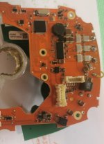
Sorry for highjacking the topic. First-thank you for it. It is a great resource for people with problematic motors, that want to salvage their systems. I found this topic while researching what kind of controller should I buy for my problematic freewheel Impulse EVO RS system on a Focus Thron ebike 250w 25km/h 92Nm 630Wh. The bike had several downtimes for its 2600km life, primarily software ones and torque sensor ones but it's still running and in pristine condition-bike parts are great and rides great, battery is still 100% healthy and has great range, motor is mechanically looking great-no broken freewheel paws, no bad bearings, no water ingress, gears are not stripped etc. The problem that I cannot resolve is with the power delivery. For the last 700km you have to press hard in order to get going and keep low cadance and pressure on the pedals to get good power from the bike. The power delivery bar (it has one) rarely goes over the middle, in the past it reached the top at steep hills. So, I am not a total electronics noob, but the logic board of the motor is way over my level of expertise. It looks very well made but it is full with tiny components that are lacquered for water proofing and it is imposible for me to check any components, besides the 2 capacitors, which seem in pristine condition (measured with an ESR meter).
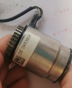
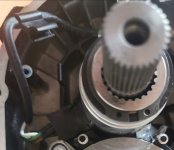
So the torque sensor is the same as you described your Boch's one, but some proprietary make of Derby Darum company and no way to source a replacemnt. It is a cylindrical one placed between the cranks' axle and the freewheel that engages to the main big metal gear. It has three wires- White, Brown and Green. When removed I can only read resistance between leads-15,5ohm WtoB;15,5ohm WtoG;30ohm BtoG. I can't see how it could be broken. There is not a lot to break there. There is a small hall sensor, or inductive sensor on the Main big metal gear that basically should read the forward rpms of the cranks, after the freewheel. It also has three leads. The middle one is Ground and I should measure the rest while powered on.
So I want to fix the bike since ever, bit since it is this closed system without any support in my country I am now planning to bypass its controller and use an external one as you did. I was planning of using a cheap Chinese sensorless one, as there are no hall sensors on the motor at all and use a thumb trottle plus keeping the original board for communicating to the battery, so that I don't need to swap the BMS, then I read your post and now I am considering bying a good controller as you did, so I could have better flexibility and possibly re-use the torque sensor, instead of thumb trottle, if the problem is outside of it. I would probably have to open a new topic, but initiall advices are welcome.
 
Here are some pics
 

Attachments

  • IMG_20200503_100633.jpg
    IMG_20200503_100633.jpg
    92.4 KB · Views: 2,274
  • IMG_20200503_100550.jpg
    IMG_20200503_100550.jpg
    157.3 KB · Views: 2,273
  • IMG_20200503_095845.jpg
    IMG_20200503_095845.jpg
    111.4 KB · Views: 2,274
  • Screenshot_20200503_095810.jpg
    Screenshot_20200503_095810.jpg
    148.8 KB · Views: 2,274
Update: I just measured both seonsors and it seems that the Hall(cadance) sensor is acting up. It reads 3.3v over COM at rest and 0v when metal is nearby, but randomly reverses reading and shows 0v at rest and 3.3v when metal is nearby.I don't think this is normal. It has 3 pins :Signal, COM, and power. It is powered with 3.7v, so I will look for replacement with same specs, as I don't think I can find the same one. Troubleshooting video https://youtu.be/w_JunO6Tprk

Update: it seems that it is not an ordinary Hall sensor, but a gear speed sensing element that could have many different features, such as built in rear earth magnet, zero speed sensing, auto calibration, auto gain, EEPROM programming, etc. So long for my plan to find one with the same specs. I am failing back to buying external controller such as VESC, as this would give me more control and I would be able to use thumb throttle and higher speed.
Is your Bosch bike still working fine with the VESC?
 
Hi Kosio86,

if your torque sensor was damaged i would expect it to either give more power than usual for pedal effort, there are reports elsewhere on es that talk about failing torque sensors and when their spring gets weak or crushed by the elephant legged individuals who can stomp harder than the manufacturer counted on. but they die by becoming more and more sensitive to the push and yours is not doing that. torque sensor is easy to impliment in the vesc as the throttle curves are completely tunable they can be made logarythmic instead of linear and the ramp start and end volts can be specified as can an inverse sensor voltage curve like the bosch one has, pedal pulsing can be ironed out by changing the polling interval for the sensor to a smidgen longer than the low torque period of pedal top and bottom rollover i found about the magic number was between 15 and 20 hz for polling frequency otherwise it was annoyingly slow to adapt to the power demand your legs are asking for... a flipsky vesc 4.2mini would be my recomended option more power would go unused as the plastic gears can only take about 600w sustainably they will eat more for a while but turn the plastic gears to peanut butter quickly. i would highly recomend installing an ntc temperature sensor inside the motor windings so the vesc can do thermal power reduction and you can never cook the little tiny motor
 
Thank you for this thread. It is full of interesting and valuable info. :thumb: I'm only using throttle on my build, but because of your effort I can see that using VESC with torque sensor is doable. This is great. The only thing is that we can only go with either throttle or torque sensor and not both working together. With some luck Benjamin Vedder, VESC creator, will implement that option. It is on his to do list.
 
mechhead said:
Hi All, new project time.

Bike: Corratech e-power e28 hybrid, bosch mid drive, alfine igh and hydraulic rim brakes.
problem: controller is bricked by wrong one time initialisation code, now gives error 500
slution: gut controller and install enerton vesc foc box controller.

I will start by disconnecting the phase wires from the motor and installing a temp sensor and new phase plug, add a vesc and bypass the bms for a direct feed.

It will hopefully run sensorless as the bosch uses a single hall sensor and a magnetic code wheel on the shaft end that ill bet does not have the same pole number as the motor and is therefore junk. ill try leaving the factory controller intact without phase connections so the lighting circuit may still work. the pack is 4p10s LG MG1 2900mah 10a cells so ill try for 800 watts to start with to keep it under half the c rate of the cells.
Tomorrow illl get the vesc and battery conections soldered up and have a play with the start up boost settings until it hopefully works and post some photos. if anyone else has tried an alternative controller on a bosch let me know how it went.
Hi
Great project.
Did you look at the Tongsheng motor controller. There is an open source firmware for it, along with the various bafang displays. If we manage to fit it inside Bosch we can have an open source bike based on the Bosch hardware for the motor. It may bring life to some old bicycles that are laying unused now because the motor or the batery has a problem. It can also be used to fool Bosch protection again third party batteries!
 
Thanks for the great information presented in this thread @Mechhead, I am considering doing similar to my Bosch Gen 2, but the main reason is that I want to add a throttle, for occasional use. One of the main reasons for wanting to do this, is that I want to use the throttle to fill in, for a couple of seconds, on steep off-road climbs, when I can't pedal due to potential pedal strikes. Obviously in order for this to work, there needs to be a freewheel between the motor output and the pedals, however, in the 5th post of this thread you stated:
mechhead said:
major problem is the lack of a pedal freewheel system, it drives the pedals with the motor and nothing i can see can be done about that

I was not sure that this was correct, so I did a bit of investigating:

When pedalling hard in Turbo mode, particularly in a low gear & you stop pedalling abruptly, the motor continues to run for a split second, during this time you can see the crank sprocket continue to turn, whilst the cranks are stationary.

@ 2:10 in this video: https://www.youtube.com/watch?time_continue=245&v=KlJ1jRGMpjg&feature=emb_logo he mentions "the clutch bearing", whilst I have not yet disassembled my motor, having watched the video & looked at various other photos, I am pretty certain that this is the freewheel that allows the motor to run without turning the cranks, could it be that yours was seized? (The freewheel that allows the cranks to turn, without the motor is mentioned @ 20:05).

By the way, I put a (Cheap, Chinese) watt meter between the battery & the motor and maximum current draw was pretty much crack on 20 amps & max power 722 watts.
 
mechhead said:
sorry about the slow reply ...

The torque sensor, i cant remember the colour code but how i identified the wires was to measure the three wires voltages with the internal bosch controller powered up and motor apart and one is +5v supply one is ground and the third with a voltage thats not 5v is the signal, the torque sensor is a signal centre type with a no torque value of aprox half a hall sensor output range (2v) and it reads negative or positive torque above and below the the voltage center of the sensor out put range. this is a little tricky to program the vesc to accept this signal you have to use the throttle ramp beginning and end point voltages to adjust the controller to get a correct reading and the torque sensor voltage goes down as pedal force increases so the throttle has to be set to reverse voltage type in the software as well.

To connect to torque sensor to vesc use the hall throttle inputs +5v G and signal
i used 1.9v zero throttle to somewhere between 0.9 and 1.1v for full throttle as an inhuman amount of pedal force is required to get the torque sensor below about 0.8v

then use a logarythmic throttle ramp to get better progressive feel and balance between pedal force and motor powerlevel
then play with play with throttle ramp max voltage to get full motor power at your desired level of force input on the cranks so it does not tire you out too much to demand full power

one problem was motor power pulsation with pedal angle force variations to solve this i played with first the sensor polling intervall, ther eis a trade off between delayed motor cut response and more /too much power pulsation, the best balance i found was to poll the sensor about 17 times a second this is fast and if the motor is a freewheeling type it could be musc slower but for the coaster brake verison if the motor stop delay is too long it kicks the pedals around for a time after you stop pushing them which really sucks . I hope you have the freewheeling version of the bosch motor

plastic motor gears sound really strained after with more than 30 motor phase amps an i suspect they will die quick at higher power levels


the torque sensor is not in the bb axel it is mounted to the idler gear carrier that conects the pedal shaft to the concentric output sprocket shaft so it does not see motor torque, you can vary the sensor v by gently levering it in the pedal forward loading direction
Thank you for replying to my questions.
This is all good stuff and I appreciate your efforts.
 
In reply to limbs query ; the version i was working is the rare one built for a back pedal braked rear hub and has no freewheel so the kick on was a real problem, for one with a built in freewheel a lower sensor polling frequency and or slower power roll off ramp would be fine.
 
mechhead said:
In reply to limbs query ; the version i was working is the rare one built for a back pedal braked rear hub and has no freewheel so the kick on was a real problem, for one with a built in freewheel a lower sensor polling frequency and or slower power roll off ramp would be fine.

Thanks for the reply & explanation, I currently have a "normal" Gen 2 in bits and can confirm that it has a freewheel. I am going to attempt to use either a BaseRunner or a PhaseRunner, in addition to a Cycle Analyst, utilising both the torque sensor and a throttle, will create a new thread if I succeed.
 
@mechhead If I understand it correctly, you use a VESC 4.12 in sensorless mode with the Bosch motor. I would be interested to know if you use sensorless BLDC mode or sensorless FOC mode and whether you experience cogging when the motor starts to assist at low RPM? I'd be interested to do the same i.e. most probably run the VESC in sensorless BLDC as I heard about issues in FOC with 4.12 but I wonder about cogging issues. Does the motor feel as smooth with the VESC as it was with the original Bosch controller?

Thanks!
 
Vielen Dank for this valuable Information !
Living close to the Bosch division who has created the mid drive, i have to climb a hill driving home from work which was the reason for a Bosch engineer to create one of the first ebikes in 1983
https://www.stuttgarter-zeitung.de/inhalt.im-stadtmuseum-gerlingen-mit-der-kraft-der-batterie-zur-schillerhoehe.db559962-53c0-442b-8d23-1f7fb87fe080.html

I`m a little mad at Bosch because they do a lot to prevent people from repairing the unit.

There is a sinus/cosinus encoder on top of the engine shaft (KMZ60). Is it possible to include the sensor into the vesc and does it make sense at all ?

Breaking the 25 km/h speed limit is not intended but if I can make the drive react as smooth as my R.I.P. electronics I have other ideas for improvement part of them beeing announced for the 2022 Bosch drives.

Thanks again!
 
The VESC does support sin/cosin encoder so it should work no problem. I have done this mod too and I just use HFI. It works well but of course it can be heard slightly.

I would try the encoder if you haven't deleted it.
 
Back
Top