Brushless DC Motor - Wye to Delta Wiring

thendless

10 µW
Joined
Jun 10, 2020
Messages
5
Hi, I am trying to wire my motor from a Wye to Delta configuration. I am wiring it in accordance with the many references shown:
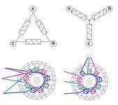
MotorDeltaWye4.png
I opened up my motor and found the following:
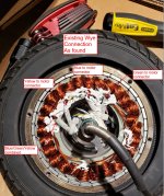
Motor Wye.JPG

To achieve a delta configuration I am supposed to wire it like this based on the diagram:
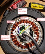
Motor Delta.JPG

Is that correct? I tried doing this configuration however the motor does not spin freely anymore. Does more need to be done that just terminating according to the above diagram?
 
At this point the drawing on your last photo indicates either (not certain which) that you haven't changed the wiring, or more likely that you've only shorted all the windings together by connecting all the phase wires to the same point, which gives you nowhere to hook up the controller phase wires, except by shorting them all together too (whcih typically results in controlelr destruction when it's powered up and operated).

In order to wire as delta, you have to disconnect both ends of each phase.

Then you have to connect only one end of each two phases together. Meaning:
--you connect Y and G at one end of each of those.
--The other end of Y connects to one end of B.
--The other end of B then connects to the still-unconnected end of G.

If you have any connection that involves three phase wires at the same point, it's not done right. ;)

Then you connect one controller phase wire to each of the three connections you made above--one goes to YG, one to YB, and one to BG.


Note that the motor phase resistance is now half of what it was, as far as the controller is concerned (I think the inductance is too?), and some motors are already low enough that some controllers will then have a problem with that and fail to operate correctly.


Hopefully you'll reply to *this* thread so we can further assist you or at least know if you solved the problem or not (you didn't reply to the previous one so we still don't know the results there, or what specific equipment you had to further assist you with it).
 
Hi Amberwolf, thanks for your reply. What you describe is exactly what I did and what is drawn in the last diagram. I will have to double check my connections to ensure it is this way again.
 
Got it working. My theory was right but I made a wiring mistake. Thanks for your help and takng the time to respond.
 
I did this to one of my motors and noticed that the phase wires getting a lot warmer than normal. If you're using a higher phase-amp controller to bring the torque back up to where it was previously (wye > delta decreases torque per amp), you might want to upgrade the phase wires running to the motor.
A temperature sensor isn't a bad idea either. Since you'll most likely be going faster, the motor won't have time to rest once the RPMs get up to the design speed. It will just keep pulling amps. My motor originally topped out at 30 MPH. Doing this mod made it go 40 but it got to 100°c in about 5 miles.
 
Hi Thor, the controller I am using is limited to 25A so I assume this will be the limiting factor. Did a 30 km test run yesterday and although I didn't have an IR gun I was able touch and maintain contact with the motor immediately after I was done with my hand for easily in excess of 10 seconds, could have held longer so I am pretty certain I am at or below 80C.
 
You're probably safe. Overheating issue I had was with a similar sized motor and a 40 amp controller.
 
Back
Top