Build your own CD battery tab welder for about $100.00+-

The limit of rate of change of current is twofold, electrical (the equivalent series resistance of the capacitor) and mechanical (the electrostatic forces on the plates). The latter can be ignored, for practical purposes, and you can safely charge capacitors as fast as you can discharge them.

I charge mine at around 7 amps peak, which seems fine. If I had a bigger power supply available I'd charge at a higher current, to reduce the cycle time.

I no longer use my tab welder, as any future cells I buy will be either pre-tabbed or have screw terminals, but it was an interesting build.

Jeremy
 
I no longer use my tab welder, as any future cells I buy will be either pre-tabbed or have screw terminals, but it was an interesting build.

Want to sell it? I was particularily impressed with your electrode press.

-JD
 
It'd cost more to ship it half way around the world to you than it's worth, to be honest, plus I took the press off after a while and switched to hand held electrodes, just because they speeded up the process, so the unit now is just a box with the capacitors, relay, and thyristor, plus some big wires and copper electrodes.

I think I'll hang on to it for now, in case I ever need to repair some un-tabbed cells in the future.

Jeremy
 
I have most of the parts to build one but ended up on using pre-welded cells. Anyone interested in the parts? I have caps, copper rods for electrodes, big SCR, etc.
 
webfootguy said:
I have most of the parts to build one but ended up on using pre-welded cells. Anyone interested in the parts? I have caps, copper rods for electrodes, big SCR, etc.

I'd be interested in your cap if you have actually measured it and it is actually about 3 Farads.

Thanks for the heads up.

Dave
 
You guys are doing amazing things!
One question, maybe a little bit of topic or already answered:
How much amps is the caps really producing between the electrodes?

Thinking of doing a wireless version...
Maybe it is possible to replace the caps with LiPos?
My ack is 14.8V, 10Ah, 30C discharge. Peak amps calculates to 300A.
Yes I can charge the caps with my ack, but I guess there is enough peak power in the LiPos? Anyone tried?
I am fully aware of the risks with LiPos, exploding and so on. Have used them and A123s for a long time in radiocontrolled car racing, where peak amps is sometimes more than 100A over 5 seconds.
 
amps would be limited only by the ESR of the capacitors and the closed loop resistance of the wiring. but with good caps and SCR it would be in the thousands of amps but only for a very short period of time.

rick
 
The simple answer is that even a pretty poor capacitor will deliver more peak current than a LiPo can do safely. As Rick says, the peak current from even a fairly small capacitor will be in the thousands of amps region.

Using a LiPo pack to charge the capacitor isn't a bad idea, as it would reduce the cycle time. Coupled with a low current charger to keep the LiPos topped up and you'd have a pretty fast system.

Jeremy
 
I'm doing increasing numbers of sub-C battery packs with my welder now. Have ordered several pieces of the sheet stock ( 6" x36") from Admiral Steel. Found that freight and handling, about 20 bucks, was the same for 5 pieces as it is for one piece so ordered 5. In the meantime, I've set up some adjustable stops on an old paper cutter to contol the cut widths. Seems to work well on my Sunstone stock.

I'm finding that electode adjustment and pressure are super critical. It is also critical to have the tips in good condition as regards diameter. It does not take too much deviation in any of those parameters to alter the quality of the weld. The most often seen shortfall is that one of the two welds may hold poorly or not at all.

I can tell a lot about how strong the welds will be by watching and listening. The best welds will show a small spark at each electrode. If only one electrode sparks, it will usually be the same one - - and the one that doesn't spark may be either a weak weld or no weld at all.

Too much pressure on the electrodes will dimple the tabs as well as the battery. This greatly increases the area over which the high current is dissipated and results in no weld. I can tell it is happening by the sound of the welder - - just a grunt, with no spark or snapping sound. Very frequently, one of the electrodes will stick slightly to the tab. Interestingly tho, it doesn't seem to have much effect on the electrode. I can do a typical battery pack without having to re-polish the electrode tip - - just a few stokes with fine emery cloth.

I'm surprised at the number of people reporting good results with the hand held electrodes. I have the impression you'd have to press pretty hard on the electrodes to get a good weld. I'm finding that my arbor press platform needs to put quite a bit of pressure on the electrodes to get a good consistent weld. In the same regard, I'm also surprised at one of the videos on the net that is on the web page of a battery rebuilding outfit - - The guy is doing a De Walt drill battery pack and it looks like he just barely touches the electrodes to the tabs - - maybe he is using a lot more force than it looks like. It appears that he makes 10 or 12 welds in about 5 seconds - - very fast.

Would sure be interested in some comments on these issues.
 
I received my new sheet stock from Admiral Steel. Pretty disappointing - - The pieces were in a folded piece of cardboard, and then strapped to a wooden board. However, it looks like they were treated to a lot of sloppy handling before they were even packaged. Lots of bends, creases, curled over edges etc. Not the quality of polish that the Sunstone strips have by any comparison. Sadly too, I bought 5 or 6 of the 6 by 36 inch sheets - - will be fighting them for some time.

My procedure is to take a full sheet and cut it into strips about 1 1/4 inches wide - - yielding about 30 plus pieces that are 1 1/4 by 6 inches. Then I cut the smaller strips into tabs that are 1 1/4 by 3/8.

I've found that I can do a passable job of smoothing out the flaws by "ironing" the 1 1/4 by 6 inch strips. I have a table saw with a heavy cast iron table that is very nicely ground - - very smooth and flat. I lay my strips on this flat surface and roll them out with a heavy steel roller that is designed for rolling formica and similar laminates down after they are cemented to a countertop. The roller is solid steel, about 2 inches wide and 2 inches in diameter - - on a very sturdy handle.

I've also started a new round of modifications to my welder. Basically, I've modified the mounting of one of the two electrodes. It now has about .125 inches of vertical movement which I have spring loaded. All this in an attempt to do a better job of equalizing the electrode pressure on the tab to be welded. This is a work in progress and I'll try to report the results as I go along - - if anyone is curious.
 
Rick's right, labour is where the cost is, plus you'll have to hunt around to get all the parts for under $100. I think the parts for mine did come out to around $100, but that was with a few hours hunting around on places like eBay to find them.

Build time was around 15 to 20 hours, including time spent sourcing the parts and doing the various modifications and adjustments needed to make it work well.

So, the total investment in money and time to build one, in a housing so that it would be reasonably safe for a non-EE person to use, is probably close to $100 plus maybe 15 to 20 hours labour. I don't know what basic labour rates are where you live, but here in the UK the legal minimum wage for the lowest paid unskilled workers is around £5.80 (~$8.70) per hour. My employer charges my time professionally at £115 (~172.50) per hour. Let's say that a labour cost that would be reasonable sits somewhere between these two values, at the lower end, say $50 per hour.

The total cost would then be around $100 for parts plus around $750 for 15 hours labour. If I charged at the rate my employer charges for me, then the labour cost goes up to a massive $2600; or, if I decide to charge at the UK minimum manual workers wage then I get a labour cost of at least $130.

Add in to this equation the issue of liability (this thing has the potential to be hazardous) and safety certification (I'm pretty sure there are laws here in the UK governing the safety of any mains powered equipment) and you can probably see that it's not really practical for someone to make you one and sell it for less than the price of that Chinese unit on eBay.

Whichever way you look at it, it's only possible to do what the title of this thread says if you do as it says, build it yourself. There are plenty here who would offer help and advice, so, if you chose to build one you'd not only get a cost-effective bit of kit, but you'd also learn a bit and get a sense of achievement from doing something way outside your personal experience comfort zone.

If you just want to build some packs quickly, then I think you'd be best biting the bullet and buying an expensive ready made welder.

Jeremy
 
I suppose it might be timely to point out the hazards of this stuff that we're all playing with. I think some of us who have worked with electrical stuff for years tend to not state the obvious when it comes to assessing hazards, maybe we take it for granted that those reading what we scribble will understand all the risks.

I know that I take risks when working with electrical stuff that many would fight shy of, but I also know that I understand those risks and take them in full knowledge that what I'm doing could kill me. My wife is now used to me working on live household circuits with insulated tools and gloves, but she used to have a fit seeing me replace light fittings etc without pulling the household fuses first. The daft thing is that I only really do it because I can't be bothered to deal with the consequences of turning the power off, like having to go around resetting clocks and programmers all over the house!

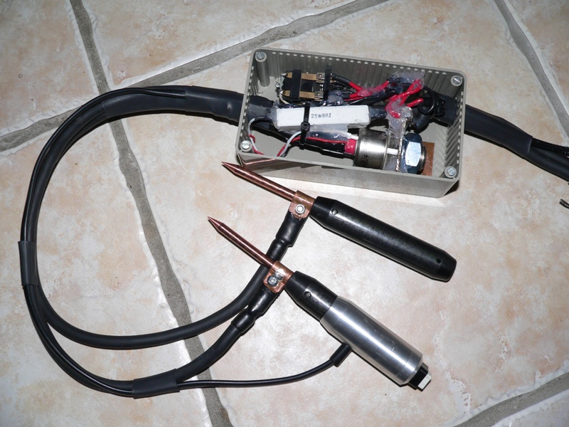
When I built my tab welder I built it for myself. It doesn't comply with the letter of the safety legislation in the UK, but is safe enough for someone like me, who understands the risks, to use. The voltages are low and all the mains powered parts are in a box that is reasonably well insulated from accidental touch. If someone with a limited understanding of the risks and technology asked me to build one for them, then, if I'm honest, it wouldn't be the cost of my time I'd worry about, it'd be the legal liability that I would be exposing myself to if something went wrong, maybe because the user didn't understand the risks properly.

I believe that, in some places around the globe, there's such a thing as a "hold harmless" agreement, essentially a bit of paper signed by the vendor and the purchaser that limits the purchasers claim on the vendor in the event of an accident. Here in the UK such agreements are useless, as our law doesn't recognise them and would consider such an agreement to be an unfair contract condition. For this reason I'd not really even want to give away any electrical equipment I'd made that had the potential to cause death or serious injury. Anything working at more than about 60V would come into that category here in the UK, in other places the limit may be different.

Mighty Volt, I can understand your reasons for not wanting to go down the DIY route, if I were in your position, with your level of confidence in working safely with high power electrical stuff and the experience of a nasty electrical accident to a close family member, then I'd probably think the same way. The bottom line is the one of price though, as Oatnet has said. DIY saves a heap of money on stuff like this, for all the reasons we've highlighted. If you don't want to go down the DIY route, then I guess you will end up paying more, unless you get lucky and pick up a bargain.

Jeremy
 
That's handy, I sort of assume that most folk on here are at least 3 or 4000 miles away, rather than just a few hundred. Postage to Ireland should be more reasonable than to the US, at around €16 non-tracked or around €26 tracked, I think, using the cheapest rates I can find, so the total cost for the bits I can supply would come to between about €35 and €45, depending on shipping option chosen (it still costs as much, or more, to ship it than the bits cost!).

Essentially I can build you the discharge and control part, from components I have. This will be a relay, to disconnect the power supply from the capacitor during discharge, a push button to fire the welder, a big 180RKI40PbF thyristor, a pair of copper rod probes and the necessary leads to hook it all up. I'll assemble everything and test it, using my power supply and capacitor bank. What you will need to do is source a suitable variable voltage power supply (0 to 15V, or maybe 0 to 20V, should do, with a current rating of at least a couple of amps, more if you can manage it) and also source a suitable car audio capacitor (a read through this thread should give an idea of those that have worked OK for others).

What you'll get from me will be a small box containing the wired up circuit, with labelled leads that you will have to connect to the capacitor and power supply. This box will have the probe leads (around 0.5m long) and probes (with handles) already connected up to it.

Although I can test it all at this end, there is a chance that you might blow something up, although having blown a few bits up I can say that it's more startling than dangerous. The thing will work OK, but won't be 100% fail-safe from operator misuse. For example, pressing the "fire" button before the probes are in contact with the work piece will certainly result in a big flash and a blown thyristor (guess how I know that!). I have a few spare thyristors, but they are the big expensive bit!

I'll PM you when I've sorted all the bits out.

Jeremy
 
OK, here's an update.

I sorted out some spare parts I had, spent a few hours out in the workshop and have knocked this sub-assembly up for you:

4426784020_ce205ebeb3_o.jpg


This is the control box and welding electrodes, with the lid of the box taken off. It's has the big thyristor (bottom right), a gate resistor (centre) and the power isolation/triggering relay (top left) in it. The leads coming from the left of the box go to the electrodes, one of which has the fire button inset into the top of the handle. The cables are reasonably flexible, they are bits of 16mm² welding cable I had going spare. For scale, that box is 150mm (~6") long and 80mm (~3 1/8") wide. The leads coming from the right of the box are the capacitor leads and the smaller power supply leads.

4426784024_ceaffa04a8_o.jpg


The big leads in this picture bolt to the top of the capacitor, red being positive. You'll need a suitable capacitor, but there's plenty of information in this thread about the pros and cons of various makes. A decent car audio capacitor will do the job nicely, I think. The small leads go to a suitable power supply, ideally a variable voltage supply capable of delivering at least 2A, preferably more, over a voltage range of around 10 to 15V. Again red is positive, hooking either the capacitor leads or the power supply leads up the wrong way will cause damage.

I've tried to ensure that everything stays put in the box by bonding the parts together with silicone adhesive, so it'll tolerate going through the post without damage. All I need to do now is wait for the silicone to fully cure and then hook it up to my capacitor and power supply and do some test welds to make sure it's OK.

Jeremy
 
Jeremy that only leaves the issue of reverse polarity protection. especially for that big cap. depending on cap construction that mayor may not be a major concern.

if the Capacitor is a large conventional electrolytic or a bank of conventional units, connecting it in reverse can have some serious consequences when it overheats and the case ruptures. Hybrid car audio caps would be less of a problem. first because they normally have an external shell that will act like a shield. second, because the super-capacitor component fails in a less dramatic manner and is physically much smaller.

heads up, important safty note. make sure you connect red to red and black to black. crossing the streams is very bad. do not cross the streams. may sound obvious but many accidents are caused when someone did something obvious...

rick
 
I guess I could add a protection diode to the supply leads, but it's harder to protect against the capacitor being hooked up the wrong way, other than fitting a shunt diode/fuse to the supply.

I think I'll just add some labels to the leads to make the connections as clear as I can and include some prominent warnings on the risk of mis-connection.

Jeremy
 
It's all finished, tested and boxed up ready to go. I added some insulation to the exposed electrodes and put labels on all the wires to make it easier to connect up. I've also put a circuit diagram and some rough instructions in the box (with a plethora of warnings!).

I made a few test welds on some nickel strips and all seemed OK. The electrodes may have too fine a point on them for your purposes, but they'll need regular cleaning and re-sharpening anyway. I've made it so that you can remove the electrodes from the holders by undoing a grub screw and also unclamping the power cables. The electrodes can then be cleaned up in a lathe, or by spinning them up in a drill and filing them when the time comes.

Jeremy
 
Jeremy,

just curious, are you using the same circuit that you posted back on page 15?

rick
 
Yes, that's the one, Rick.

Using the relay has the advantages that it doesn't short the power supply when the thyristor fires and it ensures that the thyristor gate drive is only present when the capacitor is charged.

Jeremy
 
many thanks to everybody!

my first spot welder is working very well!! :D
 

Attachments

  • 201031413253_DSC04191.JPG
    201031413253_DSC04191.JPG
    37.1 KB · Views: 3,811
  • 201031413737_DSC04190.JPG
    201031413737_DSC04190.JPG
    27.5 KB · Views: 3,811
  • 201031413822_DSC04196.JPG
    201031413822_DSC04196.JPG
    21.9 KB · Views: 3,811
fabianix,

what material are you using for the electrodes? either the color balance on the photo's is totaly off or it is not copper.

i like your idea of using a Twin Carbon Arc electrode handle. nice.

rick

are you left handed?
 
Rick,

Copper is a pain to use I found. I used nickel strip, which seems to be what virtually everyone else uses as far as I can tell (apart from the Killacycle A123 packs). I never managed to get good weld with copper and had really big problems with the electrodes sticking.

The only snag with using nickel is finding good supplies here in Europe. Most have ended up buying the stuff from the US.

Jeremy
 
rkosiorek said:
fabianix,

what material are you using for the electrodes? either the color balance on the photo's is totaly off or it is not copper.

i like your idea of using a Twin Carbon Arc electrode handle. nice.

rick

are you left handed?

hi rick,

the electrodes are very oxidized copper and, as Jeremy told, copper leave a lot of material on nickel strip..I'm looking for another material (nickel?...)
About the Twin Carbon Arc electrode handle: it is nice but you have to be very carefully, both the electrode must be pressed very well
>are you left handed? sure :eek:
 
Hello everyone,

I have spent the last week reading about battery tab welders, probably around 5-6 hours a day. Trying to learn as much as I can and this thread is amazing. I read the first 13 pages and then the last 5 pages, I will go back and read the middle tonight. I used to compete in car audio about 10 years ago so I know about capacitors and hooking them up. I know a little about relays, used them to turn different accesories on in cars and also for locking doors and other stuff in car alarms and remote vehicle starters. I would like to build a battery tab welder so I can rebuild some of my cordless tool's batteries, sub c batteries Nicad and some nimh. I would like to start out with something fairly simple and then after the basic welder is working make some improvements as needed.

My problem is I'm not an electrical engineer and don't always know what materials will work for the project. I've read what parts I need and have a list together but when searching for some of them I don't always know if what I find will work or not. I would like to keep the cost down for now, just to get started and then upgrade different components later on.

I need a power supply. When looking for a power supply is there anything specific that I need to look for? I assume it has to be variable, and around 12 volts? Is there a minimum number of amps it needs to be also? Just out of curiosity, would a battery charger work? I've also read about others using a microwave transformer, do they work or is the lack of variable volts the problem with these ideas?

Then I need a capacitor, really wish I would have saved some of my old ones from car audio! I've read about so many different brands and how they are hit or miss when it comes to working as welders. Also read about computer grade capacitors of all different fareds. Think for simplicity I will stick to one car audio capacitor for now, is there a minimum fared it needs to be? I assume the bigger the better but just wondering what an entry level cap would be?

I have a ton of wires from 1/0 to 4 ga to 8 ga and smaller so that won't be a problem. I would like to get a foot switch to keep my hands free. Eventually I would like to make a hands free setup where I can use my foot to bring the electrodes down to touch the battery and then it will make it's welds, that will be thoughts down the road. Can someone link to a source for a foot control or tell me what I need to look for in a foot control?

I'm sure I will have more questions after I get all the parts rounded up but for now I just need a little help narrowing down what to look for in the parts. When I search on ebay or other places so many parts come up and I don't know what will work or won't sometimes.

Thanks for any help you can share with me, Scott
 
Hi Scott,

Most of the parts aren't too critical, pretty much any type of trigger switch will do, it sounds like you already understand about the big capacitors and cables, so that leaves just the really critical component, the thyristor. What you're looking for is the biggest thyristor you can lay your hands on, for the lowest price! I got lucky on ebay and found some big thyristors, the only snag being that I had to buy the whole lot. They weren't too expensive, though, plus it was handy to have a spare when I blew the first one up...............

What you're looking for is a thyristor rated at around 100 to 200 amps, with a peak current rating of better than about 1500 amps, the higher the better. The voltage doesn't matter, as there's no way you're going to exceed the voltage rating of any thyristor that's readily available. Ideally, you want one in a mounting style that's easy to connect to, so the puck-style ones are probably not a good idea to go for. Stud mount, or one of the bolt connection packages are probably the easiest to work with. I have some spare stud mount thyristors, rated at 4000 amps peak, but if you're outside Europe then the high shipping cost is prohibitive, as they weigh around 0.5kg. I've attached the datasheet to this post as an example of the sort of ratings you're looking for.


If you choose to use the relay trigger circuit that I've used, then you need a changeover relay. A standard car-type changeover relay will be fine, it only needs to be rated for the maximum current of your power supply, which will almost certainly be a lot lower than the current capability of even a cheap car relay.

Most of us are using plain copper rod for electrodes. I sourced some 1/4" diameter stuff fairly easily, I think it was intended for use as a ground rod.

Hope this helps. If you find a likely looking thyristor and want it checked out before you buy, just post the details and I'll take a look at it's specs and let you know.

Jeremy
 
Back
Top