Build your own CD battery tab welder for about $100.00+-

Just a big "buon giorno" from Italy to the forum.

I'm trying to build my cheap battery welder too and, from a university lab, I received two Maxwell supercapacitors.
They are rated 15V/58F (YES! 58Farad) each. Are too much powerful for our use?

Datasheet can be found here...
http://www.maxwell.com/ultracapacitors/datasheets/DATASHEET_15V_series_1009361.pdf

Any help will be appreciated :wink:

P.S. Just for info... those 58F (Active balanced) ultracapacitors cost about 150Eur in Italy... not so much...

--
Cesare
 
Welcome Cesare.

I think that you may find that those big Maxwell capacitors are too big. Although you could compensate for the high capacitance by reducing the voltage, I think that you need several volts to ensure that the initial cleaning stage of the weld process works OK. You may find that you need to reduce the voltage to the point where this voltage-driven cleaning effect is less effective, which may result in poor welds.

Jeremy
 
maybe a stud welding Gun can do the job with some modification it can hold lot of pressure with a single welding spot and the heat is not to hot after fews second you can touch the surface

sorry just an idea i am not a electronic expert but a ex bodyman
 
Thank you Jeremy,it's all clear.

But which is the current/voltage I need for a good welding?

Those supercapacitors can give 80A of continuous current 1sec@15V, 1500A peak.

Need a little further help... :)

--
Cesare
 
Cesare,

Based on what we know works well, you need between 10 volts and 20 volts with a capacitor of around 2F to 4F. This seems to give the right sort of discharge current to give good welds on battery tabs. The actual weld current will be very high, a few thousand amps, but the pulse duration is short, so the heating around the weld is small.

The capacitors ideally need to have a low internal equivalent series resistance, ESR. Most good quality car audio capacitors seem to be up to the job, as are good quality computer power supply capacitors.

You really need to be able to adjust the capacitor charge voltage, using a variable voltage power supply, to allow the weld energy to be set for the particular type of battery terminal and thickness of nickel tab.

Jeremy
 
Thanks again, Jeremy.

I think I will try with those Maxwell Supercap.
Actually there's a couple on Ebay with a very affordable price (less than 30Eur each...).
They have a very good ESR of 0,019ohm and they are used in telcon or critical appliances.

I've a good power supply, regulated in voltage and current, so no problem on that side (I work with highpower leds....).

I will try and let you know, as Maxwell had a very good list of supercaps, good prices and industrial specs (52F supercap, for example, has an ESR of 0,0015ohm.... :D ).

See you soon!

--
Cesare
 
52F is very, very big, probably massively too big for a CD welder for this application. I can blow holes in the end of cells with just under 2F at 20V, which equates to about 400 Joules of energy. Even at the lowest practical voltage for a welder of this type, around 10V, a 52F capacitor would deliver 2600 Joules; charged to 20V a 52F capacitor would deliver a massive 10,400 Joules, around 26 times more than the maximum you need.

The big risk with using the big capacitor/lower voltage approach will be heating. The weld current pulse length is determined by the total circuit resistance and the capacitance, rather than the voltage. If we assume that the total circuit resistance is around 30mohms (capacitor ESR plus wiring and weld resistance loss), then the weld current time constant will be 1.56 seconds, which is massively too long. The weld needs to take only around 50mS to 200mS, which would be achieved with a capacitor of between 1.6F and 6.7F.

This weld process works well on thin metal because it is quick and doesn't last long enough to damage the cell or excessively melt the metal around the weld area.

Jeremy
 
Jeremy is doing a great job of being polite and patient. The kind of current that can be released from 50 farads is awesome and can be incredibly dangerous. This is an elephant gun approach to swatting a gnat.

As the cliche goes, "Don't try this at home!!"
 
OK, I understand.

DON'T do this at home.... and I follow the kind guide.

So, what about these (little) 5Farad from Maxwell?
http://it.mouser.com/ProductDetail/Maxwell-Technologies/BCAP0005-P270-T01/?qs=8v%2fozMoygqMddqGFEfW5Fw%3d%3d

Still too much? I was thinking about 7/8 in series...

Let me know and thank you for helping-

--
Cesare
 
OK, I'll go through this one more time, then, I'm afraid, I'm out of this thread, as you seem to be intent on going down a path which is wholly unproven and fraught with problems, rather than follow the advice of the many on here who have worked out the best way to build one of these things..

The ignored advice given so far:

The capacitor needs to be around 2 to 6F, probably 2 or 3F is optimum if you have high quality capacitors. It needs to have as low an ESR as possible, preferably much less than the remainder of the circuit resistance, or else large amounts of power will be wasted in the capacitor (which may not be able to cope with the heat build up over time as you do multiple welds). It needs to be charged to around 15V, with a variable voltage supply to allow for weld power adjustment. Car audio capacitors have been proven to work well, as have big commercial grade low ESR electrolytic capacitors.


You seem to be intent on using capacitors that are quite clearly unsuited to the job and which have never (as far as I'm aware) been used in this way. The capacitors you've pointed out could be connected in series, but you would need to find a means to ensure that they each stayed within their voltage limits. This may well mean using some form of shunt system to limit the voltage across each capacitor. Let's do some very simple arithmetic on your choice:

The Maxwell BCAP0005-P270-T01 is rated at 2.7V, 5F, 0.2ohms ESR.

Let's say you put 7 in series; that gives you a capacitor with a capacitance of 0.714F with a voltage rating of 18.9V and an ESR of 1.4ohms.

Assuming that you can charge and discharge these safely when connected in a series string like this, and assuming that you use a 15V charge voltage, the peak current that you could get from this set up would be just 10.64 amps (15 / 1.41) when discharged into a typical weld circuit resistance of around 10mohms. You need hundreds, perhaps over a thousand, amps to make a good weld.

Around 99% of your weld energy would be dissipated inside the capacitor with this set up, due to the very high ESR, with only around 1% actually going into the work piece.

Now, let's compare this with all the good advice from here that you keep ignoring:

Take a good car audio capacitor. It will typically have an ESR of around 5mohms or so, maybe less. Charged to the same 15V and discharged into a circuit with a resistance of around 10mohms, it will deliver a peak current of around 1000 amps (15 / 0.015) and only waste around 30% of the weld energy inside the capacitor. What's more, we know beyond any doubt that this set up will work and make good welds.

Please feel free to experiment, all we're trying to do here is save you from making mistakes, wasting money and perhaps having an accident by pointing you towards what we know works.

Jeremy
 
Jeremy,
in this last post you've summed up all my ignorance and you gave all the answers I and every newbie needs.
Thank you again for be patient.

When I'll realize the welding machine, I'll follow your guidelines.

And I will continue to develop my high power led systems.... ;)
Do you need one?

--
Cesare
 
The Mighty Volt said:
Rick, at what point, in terms of voltage, does the pre-existing current become a real threat? You think it it needs to be 50v or more? We are talking pretty serious current with these welders. Thanks

sorry no easy answer to this question. it takes a combination of current and voltage to do damage. and then it depends on what parts of the body are carrying that current. also it AC or DC? DC usually causes a single muscle spasm that will jerk you away from contact while AC tends toward a muscle contraction where you grab and prolong the contact.

at little as 10mA or 0.010Amp carried through the organs of the chest can stop your heart. carried acros the surface of your tounge this just provides an interesting tingle. just lick the top of a 9V transistor radio battery.

as always the laws of physics govenrn this. Volts = Current times Ohms. if various parts of the body are a certain resistance and damage occurs once a threshold current is exceed, obviously it is easier to exceed that threshold at a higher voltage. and at 50 or 60V we get to the point where depending on what part of the body it is and whether it is wet or dry it becomes relatively easy to cause burns.

regardless of the voltage injuries may secondary and may be caused as a result of other damage. if i short a car battery with a wrench, it melts, starting a fire, and the fire kills me. what actually killed me? the fire? or was it the electricity that shorted the wrench? in this case it was ONLY 12V but at very high current melting the relatively low resistance metal of a wrench. even if a fire did not start i could still severly burn myself by reaching for that very hot wrench.

short answer here is that given the relatively high resistance of dry skin 12V by itself is not that dangerous. on the other hand 12V at very high current through the electrodes can melt metal. now that melted metal or hot spot become their own safety concern.

rick
 
The nice mailman brought me my SCR today!!!

This thing is pretty big. The ebay add says 1600volts 9000A(10ms). So now all I need is my capacitor which I have narrowed down and just need to hit the buy it now button.

Has anyone mounted all the components in a nice little metal or plastic box? I saw the guy that used an old welder frame. I was wondering if someone knows where to get a cheap enclosure to mount everything in instead of laying all over the bench? I was thinking of mounting everything and putting some cooling fans in and some sort of terminals on the front to hook the electrods up to. My work bench is pretty crowded so would be nice to try and keep this organized and be able to move it if needed and not have wires laying all over.

Scott
 
Sounds pretty good so far.

My capacitors, thyristor and trigger circuit are fitted inside a wooden box that doubles up as a work surface for welding cells. Here's a couple of photos from earlier in this thread:

2618306836_eae99285f6_b.jpg


This is the bank of capacitors with the thyristor

2617482299_8cf441ffcf_b.jpg


If you ignore the alloy frame etc, then you can see that I just fitted all the electronic bits (except the power supply) inside the wooden base.

The unit currently doesn't have the alloy frame fitted, the welding cables just come out of the base to a pair of hand-held electrodes.

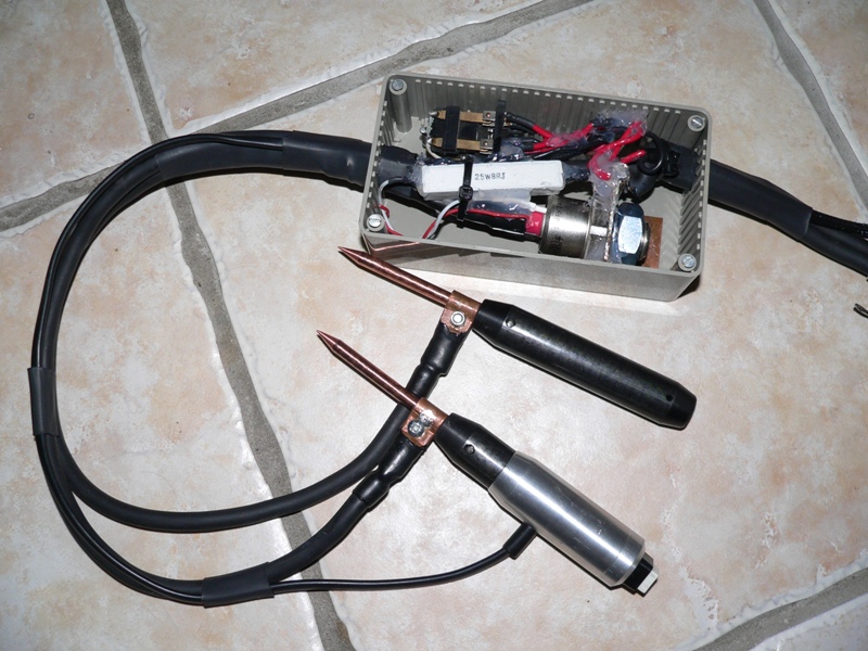
An alternative would be to do what I did when I built the discharge unit for The Mighty Volt. I just used a plastic project box and fitted the thyristor and trigger components inside. The capacitor and power supply just hook up via a couple of cables. Here's a photo:

4426784020_ce205ebeb3_o.jpg


Jeremy
 
I will look for a project box and see what I can come up with. Maybe the local hardware store has a bigger plastic electrical junction box for a reasonable price I could use. Will have to do some searching and see what I can come up with.
 
n93cx.jpg


This is the power supply I have settled on.

Technical Specification

Specifications:
Input voltage: AC 230 V
Output voltage: 1-20 volts, user adjustable at 0.1V intervals
Output current: 0-5 amps, user adjustable at 0.01A intervals
Voltage regulation:
Load from 10% to 100% variation: 70mV
Line from AC 180 V to AC 264 V variation: 20mV
Ripple and noise (RMS): 5mV
Ripple and noise (peak to peak): 30mV
Current regulation:
Load from 10% to 100% variation: 20mA
Line from AC 180 V to AC 264 V variation: 20mA
Ripple and noise (peak to peak): 20mA
Efficiency at maximum power: 84%
Dimensions: 70(w) x 150(h) x 250(d) mm
Weight: 2kg

Only "problem" is that there is no cooling fan.
 
I picked up a UNITEK, Model 1-156-02, spot welder today that I won in a surplus equipment auction. It is a 125 Watt second machine, with reasonable adjustability. It appears to be 15 or 20 years old. I got it home and just started to look it over and clean it up.

It has an interesting electrical topology. Basically the DC bus appears to be around 0 to 100 Volts. The energy storage is in Qty 6 2250 uF 150 VDC commercial grade capacitors. SCR firing the energy into an impedance matching transformer that goes to the spot welding electrodes. Secondary is 1cm x 1mm copper strap to electrodes; primary is some turns of #12 with 4 individual windings. The transformer is fairly big, about 10 cm x 10 cm x 10 cm. It is about the same size as the power transformer. Both are E I core with laminations. The marked - electrode is connected to chassis ground. [So there is no misunderstanding, the ~100 Volt storage bus is stepped down by the output transformer to the weld tips. There is low voltage/high current on the electrodes via the impedance transform.]

The welder has a 125 watt second range; and a 25 watt second range. Within each range the watt seconds are adjustable from zero to full range. Weld polarity is adjustable with electrode + or electrode - (won't make any difference when we use two electrodes.) Weld schedule is selectable between two modes: high, narrow peak with low tail and lower, broad peak with high tail.

The commercial electrode holder looks very similar to Jeremy's. The only difference is Unitek uses replaceable tips on larger copper electrodes. There is a handy thumb button to fire.

I want to replace the caps in the logic and control boards before I power it up to measure things. Also want to rejuvenate the storage caps carefully. I will take some pix's in a few days and if it fires up make some measurements of the Unitek weld schedule to share.
 
I have a qustion about my SCR. It has GE 8493623 U514 on it. Is there a way to test this out? I tried to ohm it and I thought with no power to the trigger it would be open and when you apply power to the trigger wires it would connect, is this how they work? Like a big relay? One trigger(sorry if this isn't the right term!) wire is tied in with the red main power wire and the other trigger wire is a white one that goes into the cap of the SCR. With no trigger wires hooked up it read around 20 ohms between the threaded end and the main power wire. When I sent a couple volts positve to the white wire going into the SCR it read around 1.5 ohms. Also I wasn't sure what voltage/amps the trigger wires need to activate it? So it seems to be switching on and off when I send positive voltage to the white wire. And then the red trigger wire that is soldered to the red main wire on one side of the SCR would get the negative power for the trigger and the main red wire goes to the negative post of the capacitor? In your picture Jeremy it looks like the red trigger wire isn't hooked up to anything? And do you just use the power from the capacitor to trigger the SCR?

I've used relays and big 200 amp relays for car audio but don't have any experience with SCRs so just making sure I understand it before hooking everything up.

Thanks for any advice you might be able to share
 
bigmoose said:
I picked up a UNITEK, Model 1-156-02, spot welder today that I won in a surplus equipment auction. It is a 125 Watt second machine, with reasonable adjustability. It appears to be 15 or 20 years old. I got it home and just started to look it over and clean it up.

It has an interesting electrical topology. Basically the DC bus appears to be around 0 to 100 Volts. The energy storage is in Qty 6 2250 uF 150 VDC commercial grade capacitors. SCR firing the energy into an impedance matching transformer that goes to the spot welding electrodes. Secondary is 1cm x 1mm copper strap to electrodes; primary is some turns of #12 with 4 individual windings. The transformer is fairly big, about 10 cm x 10 cm x 10 cm. It is about the same size as the power transformer. Both are E I core with laminations. The marked - electrode is connected to chassis ground. [So there is no misunderstanding, the ~100 Volt storage bus is stepped down by the output transformer to the weld tips. There is low voltage/high current on the electrodes via the impedance transform.]

The welder has a 125 watt second range; and a 25 watt second range. Within each range the watt seconds are adjustable from zero to full range. Weld polarity is adjustable with electrode + or electrode - (won't make any difference when we use two electrodes.) Weld schedule is selectable between two modes: high, narrow peak with low tail and lower, broad peak with high tail.

The commercial electrode holder looks very similar to Jeremy's. The only difference is Unitek uses replaceable tips on larger copper electrodes. There is a handy thumb button to fire.

I want to replace the caps in the logic and control boards before I power it up to measure things. Also want to rejuvenate the storage caps carefully. I will take some pix's in a few days and if it fires up make some measurements of the Unitek weld schedule to share.

Very cool! Can you try to see some tests on dis-)similar metal welding with it? If it has the power to do aluminum to aluminum, or aluminum to nickle (possible with friction welds, no idea if possible with these spotwelders, but it would be awesome to find out. :)
 
ponch37300 said:
I have a qustion about my SCR. It has GE 8493623 U514 on it. Is there a way to test this out? I tried to ohm it and I thought with no power to the trigger it would be open and when you apply power to the trigger wires it would connect, is this how they work? Like a big relay? One trigger(sorry if this isn't the right term!) wire is tied in with the red main power wire and the other trigger wire is a white one that goes into the cap of the SCR. With no trigger wires hooked up it read around 20 ohms between the threaded end and the main power wire. When I sent a couple volts positve to the white wire going into the SCR it read around 1.5 ohms. Also I wasn't sure what voltage/amps the trigger wires need to activate it? So it seems to be switching on and off when I send positive voltage to the white wire. And then the red trigger wire that is soldered to the red main wire on one side of the SCR would get the negative power for the trigger and the main red wire goes to the negative post of the capacitor? In your picture Jeremy it looks like the red trigger wire isn't hooked up to anything? And do you just use the power from the capacitor to trigger the SCR?

I've used relays and big 200 amp relays for car audio but don't have any experience with SCRs so just making sure I understand it before hooking everything up.

Thanks for any advice you might be able to share

The red wire isn't the gate connection, it's just connected to the cathode terminal. It's only there as another convenient way to hook the trigger circuit up. For this application it's not needed, as the cathode is connected to the trigger circuit directly.

The gate terminal (the white wire) needs a current limited pulse of around an amp or so to trigger the thyristor quickly. The threshold voltage needed to activate the gate is around 1 to 2V normally.

The best way to test them is probably to build the welder circuit, but replace the welding electrodes with a low value (maybe a few ohms) high power resistor. You can then charge the capacitor up, trigger the thyristor and measure the voltage pulse across this resistor as the capacitor discharges into it. This is a relatively safe way to test the circuit and components.

Jeremy
 
Thanks Jeremy.

Is the threaded part of the SCR solid? Can I drill in about 1/2" or so and tap it so I can use a bolt and ring terminal to connect my wire to it?
 
It should be solid where the thread is, as the semiconductor die will be bonded about where the hexagonal nut bit is. I would limit the depth of any hole you drill carefully, as the likelihood is that the die will be close to the threaded part.

Jeremy
 
This thread seems to have died off a bit....I would like to regenerate it by asking {a} what grade of capacitor would work best with the 20v 5A power supply I have.....i.e. 1Farad, 1.5Farad, 2Farad etc.

Also, now that we are on the topic...what is the preferred width of nickel tab for welding {a} 18650 A123 cells and {b} 22650 A123 cells.

Thanks. 8)
 
I too have just finished spending most of the last 20 hours reading every word and following MOST of the threads.

As far as I can tell, nobody has yet developed a device or technique that they are confident will work for A123 cells.

Is that correct, or did I miss it? I am curious because I wound up here after starting to research ways to build my own A123 packs, because I assumed they were the best battery for my needs. If it's not possible to do good home-welds on A123s then I will research alternate types of batteries.

Also, the first few things I read in my research were about Microwave Oven Transformer based welders, and that crowd was pretty dismissive of the SCR approach. Can anyone here explain the pros and cons of constructing the SCR type welder outlined here vs. an MOT?

Thanks to everyone who has contributed so far! It has been like taking an EE class online. I got to the point that I knew the answers to newer questions just based on what I learned here. Much appreciated.

Mike
 
Back
Top