Build your own CD battery tab welder for about $100.00+-

I don't think it's an issue of oxygen in this case. While exposed aluminum does form an oxide quite rapidly, a weld is nearly instantaneous and there shouldn't be any significant amount of air trapped between the nickel and aluminum. They're in contact so the melted aluminum and nickel should intermingle before oxides form.

All I could find online said that spot-welding aluminum is a problem due to its low resistance (requiring exceptionally high currents to produce heat) and high thermal conductivity (which removes the heat from the spot, but not such a problem with fast CD welding). But, I'm confused why I got a pit in the aluminum if there's no melting. Maybe the problem is the high resistance of the oxide surface means the current's primarily flowing through the nickel strip, but again, the aluminum's got a pit. I wouldn't expect that just from contact with the melted nickel either.

BTW, I know nobody asked, but I found A123 is tabbed with 0.010" nickel. My Yesa 20AH cells were tabbed with 0.008". I now don't feel like my 0.005" tabbing material is all that awesome.
 
has anyone gotten some solid welds on the positive teminal on the a123 cells..

i've gotten some excellent welds on the negative terminal .. however my positive terminal welds don't stick well..

any guidance would be helpfull

thanks
-steveo
 
steveo said:
has anyone gotten some solid welds on the positive teminal on the a123 cells..

i've gotten some excellent welds on the negative terminal .. however my positive terminal welds don't stick well..

any guidance would be helpfull

thanks
-steveo

Positive welds will not be of the same quality as the negatives.

Now, if you open and disassemble a 36v Dewalt pack, you will see that they have the same "problem" with their own cells. The negative welds are always far far stronger than those on the positives.
 
The Mighty Volt said:
steveo said:
has anyone gotten some solid welds on the positive teminal on the a123 cells..

i've gotten some excellent welds on the negative terminal .. however my positive terminal welds don't stick well..

any guidance would be helpfull

thanks
-steveo

Positive welds will not be of the same quality as the negatives.

Now, if you open and disassemble a 36v Dewalt pack, you will see that they have the same "problem" with their own cells. The negative welds are always far far stronger than those on the positives.

you are absolulty right!

is there anything we can do to try & get the best welds possible?

thanks
-steveo
 
So texaspyro when do the rest of us get a chance to build one of your welders ? Are you going to share and at what level, source code perhaps :)
 
texaspyro said:
You pretty much cannot effectively spot weld to aluminum. What happens is you can get a weld nugget to form and the materials bond, but the aluminum at the bottom of the nugget is very brittle. Tug on the nickel and it breaks free of the aluminum base, leaving a divot in the aluminum and and an aluminum pimple firmly welded to the nickel (or copper) strip.


It's not easy, but my old Acura NSX and my current Honda Insight are both proof that it can be done. :) both cars feature entry aluminum chassis, the bulk of which appears spot welded with beautiful round little 1/4" spots.
 
steveo said:
The Mighty Volt said:
steveo said:
has anyone gotten some solid welds on the positive teminal on the a123 cells..

i've gotten some excellent welds on the negative terminal .. however my positive terminal welds don't stick well..

any guidance would be helpfull

thanks
-steveo

Positive welds will not be of the same quality as the negatives.

Now, if you open and disassemble a 36v Dewalt pack, you will see that they have the same "problem" with their own cells. The negative welds are always far far stronger than those on the positives.

you are absolulty right!

is there anything we can do to try & get the best welds possible?

thanks
-steveo


No problem. There is one advantage in that with the greater surface area afforded to you by the positive terminal, you can bang in more welds per terminal than with the negative.

What I do is use thin nickel, {From MTO Corp} bang in as many welds as possible, then use another piece of nickel and bang that on too, again with as many welds. Once I am sure it is not going to fall off, I take advantage again of the greater surface area by soldering some copper braid down onto both the nickel tabs and the remaining exposed area of the terminal.

As you do this, try to make sure that the preponderance of the heat, if not the solder, is directed at the tabbed area, to minimise heat damage to the cell.

It is worth nothing that the thinner nickel, with more tab welds, combined with soldered copper braid, is a better solution to a poorly welded thicker nickel.

Get a pen and paper and take notes of the thickness of the nickel and the voltage at which the welds are delivered. There is a "sweet spot" between the two values. Sometimes, more is less.

I also note that nickel with a dull finish seems to take a better weld than the shiny stuff.
 
Hi guy's have a look at this page:
http://www.pittnerovi.com/jiri/hobby/electronics/welder/index.html

I have built one and it works ish (not the designers fault I may add). Mine has a problem in that it keeps blowing the weld FETs, hopefully you guys may be able to help.

It is based on the Ultrakeet design, seen here:
http://ultrakeet.com.au/index.php?id=article&name=cdWelder_p2

The caps I obtained are 10 x Mepco/Centralab 110,000uf 60VDC, all capacitance and ESR checked.

I have two suspicions for why I am loosing fets:

1) The fets came from a chap in Hong Kong via ebay, and I strongly suspect they are not genuine International Rectifier items, and therefore like all copies not as good as the originals. For as long as the listing is up you can see it here http://cgi.ebay.co.uk/ws/eBayISAPI.dll?ViewItem&item=390232455834 seller goodbuy711

2) As I have higher voltage caps I changed the fet drive arrangement to make sure the fets got fully turned on with out getting over volted. I have attached my drive arrangement for you to take a look see. I know the higher voltage may give worse welds but I felt the drive arrangement was marginal so I tinkered. The main problem is under driving of the high side charge fet, (which I am guessing is why texaspyro opted for a p-channel fet), and over driving(voltage) of the low side weld and discharge fets.

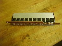
Also attached is a pic of my fets before soldering up. 8 * IRFP2907 for welding and one each for charge and discharge. I opted to couple the main weld leads at either end thus giving each fet the same amount of copper bus bar and therefore not stressing one more than the others.

Any ideas ?SV200882.JPG
 

Attachments

  • AVR Spot Welder Drive Schematic.pdf
    21.1 KB · Views: 396
Those MOSFETs look legit... but then, don't they all. If you can measure their Rds-on resistance it should be around 3 milliohms. If much more than that, the FETs are probably bogus.

I think your problem is in the gate drives. You are effectively switching the FETs in the high side of the load. When you turn on the FETs, the source is being pulled up to Vcap (say 15-20V), but the gate drive voltage cannot exceed 15V. To fully turn on the FETs requires that the gate voltage exceed the source voltage by 10V. Also, your gate drive series resistors are 220 ohms... maybe a bit high for getting through the linear region quickly.

In my welder the discharge and firing fets have grounded sources and the gates are driven by a TC428 mosfet driver chip. The charge FETs are paralleled IRF4905 P-channels driven from a 74LS06 open collector hex inverter.
 
BTW, those who sent me some PM's lately... I am still having problems accessing the PM function to respond. My browser just spins loading the page... not sure what is going on...
 
texaspyro said:
When you turn of the FETs, the source is being pulled up to Vcap (say 15-20V), but the gate drive voltage cannot exceed 15V.

Reply understood, I am guessing you meant "on" instead of "of" in the above quote. That did throw me for a while. Anyway, does my design not ensure that as the voltage rises on the weld FET source pin that the gate voltage rises as well ? Provided I don't exceed Vdrive which is always kept 15v above Vcap because the ground of the 15v reg uses Vcap as ground, given this the zener should then keep the gate 15v above the source (at least when switched on). Or did I boo boo ?

I didn't move the fets to the low side of the weld load due to ignorance mainly, I agree it seemed the sensible place to put them but every design I spotted had them on the high side so I guessed they knew something I didn't about welding (very possible) and must of had a very good reason for putting them on the high side so kept them there. texaspyro your welding pics look like low side fets manage just fine.

I do have a way of checking the Rds I will do so and report. The initial creeping thought that they might not be real IR FET's was when I went to bend one of the legs through about 45 degrees and it snapped off, real copper doesn't do that !
 
Doesn't look good for the FET's Vgs @ 11.74v, Rds = 11.8 milliohms, measured using and old military spec earth bonding tester on 199.9 millohm range.

Is it just me or do the leads look like two different metals scarf joined, brass and copper perhaps, can't imagine why one snapped on me. Doubt this is standard IR practice. Buyer beware of crap eBay FETs.

Further comments on my drive setup still welcome.
 

Attachments

  • SV200897.JPG
    SV200897.JPG
    184.3 KB · Views: 2,408
  • SV200898.JPG
    312.7 KB · Views: 2,404
Just a heads up.

For those looking for thyristors. There are some of the small type hockey puck style ones available on ebay currently that are potentially cheap.

Search for Westcode 410403-24az. They are used. But, I bought 5 for a project, and he took my offer of $10.00 each. He puts one up for bid every week or so starting at $9.99 (That's how I knew to make the $10 offer). All the ones I bought are good, and they all look like new. The original application was in Reliance/Rockwell converters. I think that they are actually new, just maybe old stock, circa 2003.

I have the datasheet for the family of these, but do not know which particular one they are. The family varies by voltage only and starts at about 1200V. Average current at 55C is almost 400 Amps, 25C almost 800 Amps. The peak current is over 5000 Amps.

The datasheet is for the Westcode N195CHxxx family. Go to http://www.westcode.com/pctc.htm, then search for n195ch. The datasheet is down-loadable from the link at the left.

Dave
 
I've gotten 3 Fosgate caps in and want to play around with this design concept. If anyone has 50 to 100 GENUINE IRFP2907's floating around they want to part with, let me know. They will be tested however, so they need to be genuine.
 
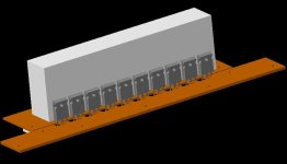
Here is my 3D model of the welder power head based on 3 Fosgate 1 Farad Caps. I succeeded in getting three off of eBay. Two were perfect, one had the lead blow off inside the case, pix below. I'm working on a fix for the leads.

For the eagle eyes, the gates on this drawing are shown going into to base copper with the Drains, that is not the case in fabrication. There will be a gate driver board snugged in between the FET's with a center hole for the electrode stud to protrude.

I will laminate my own G-10 board with heavy copper sheet, then route out the three concentric circles.

Comments welcome.

View attachment 1


View attachment 2
 
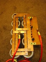
I like the circular arrangement very neat thinking bigmoose. Here is what I plumped for with my 10 110,000uF caps, I went for a single layer pcb with 3mm thick copper :lol: It will carry ten IRFP4368's. On an amp for amp basis these costed out cheaper than IRFP2907's, this time bought from a proper component supplier, still waiting for them to arrive though.
Transistor Layout.jpg
SV200906_sml.JPG
 
Very nice arrangement also diaz! ... and yours is in copper and not just a drawing like mine! Look forward to your results.

TexasP thanks for reminding me about the TVS diodes and some snubbers to deal with lead inductance.
 
Just a little update. IT LIVES ! Or at least it hasn't destroyed itself on a per weld basis as my previous attempts did. I will put some pics and the rest of the design files up when I think it's sorted-ish. I currently need to add weld energy settings, and capacitance measurement into the code. If you can't wait the design is based on Jiri Pittner's code, and Texas Pyro's schematic hints. Don't hold your breath though, I ain't the quickest.
 
You don't need to wait pyro, you already know the most part of it, and have a kick ass welder yourself. Seriously though thanks for the help.
 
Hi guys

With the help of a crazy EE from work I have made a prototype welder with a 0.7 farad cap and a dirty great SCR, with solid copper electrodes.

It welds 0.25mm Stainless shim to Headway cells just fine. Pity stainless is a crappy conductor - which I guess is why it welds so well.


But it won't weld the 0.25mm Headway tabs (stripped from dead packs) which is nickel. There's no adhesion at all between the nickel tab and nickel plated cell end.
I have another farad on the way, hopefully that will do the trick.


Does anyone have a source for Nickel shim that will ship to Australia? I'm finding it hard to source here.


Mark
 
Have you tried http://admiralsteel.com ?

Also 0.7F is rather low (assuming it is a real 0.7F). If you are using car audio caps you are probably screwed... What voltage are you running?
 
Back
Top