Build your own CD battery tab welder for about $100.00+-

Thanks very much for that, Rick, I could have done with that good advice months ago when I had my own fair share of copper drilling problems...............

Jeremy
 
Question to SimpleCJ, about your post from Wed Jan 14, 2009 1:12 pm

I see you have some Power Acoustik capacitors in the picture, and one large to the right appears to be the 10F unit, PCX-10F.
I am planning to purchase one of those, the price Dollars per Farad is the most attractive without going over the $100 limit, and keep subject of this thread possible... :D
My question is; Did you try to open that unit? how is it inside? can you take apart those capacitors? how many are there?

The idea is to disassemble such unit and build a double pulse unit, one cap for the first pulse, and the others cap as the second discharge.
It seems the unit contains 4 or 5 caps inside, but I may be wrong. I couldn't find anywhere in the net a picture of that unit open.

Thanks for any answer.
Wagnerlip
 
Hi Guys, I just finished my microprocessor controlled 600Ws Capacitor spot welder with Pulse Width control...check it out http://www.youtube.com/watch?v=yabesdeGKJo
Nemo, you are blowing your mosfets because these capacitor welders can pull up to 10 000 amps at 20v for a Millisecond or less. Amps=volts/resistance
Nickel's resistance is +- 0.003 Ohm so 20V/0.003 = 6 666 amps and it is higher when you weld copper with a very low resistance. The size of the capacitor is the time it takes to fully discharge. 1Farad cap= +-15Ms and a 3Farad cap = +-45Ms when you weld 0.003ohm nickel.
People ask why don't their 200Amp SCR's blow then......the answer is that it will blow after a lot of high voltage welds because If you look at your SCR's Data sheet you'll see I(TSM) Max. (A)=5.0k. It means the surge current is 5000Amps. If you weld nickel you can go to about 16Volt.....16/0.003 = 5 333amps and you should be okay. 2 SCR's in parallel will handle 10 000 amps and that should be safe.
I was actually on my way to bed....

:D
 
really KEWL!!!.

nice looking, pro setup. Did you use the case/chasis from an old welder or battery charger?

can't wait to see the shematics. will the code for the uP also be available?

rick
 
great stuff :D :mrgreen:
 
Great stuff and very proffesional. Actually I'm inspired to close mine inside the box now. My welder is electricaly finished . I did manadge to solve the mosfet failing. I soldered together not only a mosfet driver inputs but also their gate output. This way I can be certain that the mosfets are opening and closing at the same time and share the 10 000A or so.
What is switching on and more importantly off the pulse in your welder? SCR can't switch off once it is on. 2 SCR and a dummy load? Get the schematic together soon. I'll draw my dual pulse analog controll welder too.I'm also interested in doing some comparation tests of welding if you are interested . My 8x1.5F (12F) capacitor bank versus yours and welding time. Did you tried coper to coper? I can do nickel -copper just fine but not the other way round.
Again, a great looking welder! I'm pleased that another welder was born!
 
Fritz said:
Hi Guys, I just finished my microprocessor controlled 600Ws Capacitor spot welder with Pulse Width control...check it out http://www.youtube.com/watch?v=yabesdeGKJo
Nemo, you are blowing your mosfets because these capacitor welders can pull up to 10 000 amps at 20v for a Millisecond or less. Amps=volts/resistance
Nickel's resistance is +- 0.003 Ohm so 20V/0.003 = 6 666 amps and it is higher when you weld copper with a very low resistance. The size of the capacitor is the time it takes to fully discharge. 1Farad cap= +-15Ms and a 3Farad cap = +-45Ms when you weld 0.003ohm nickel.
People ask why don't their 200Amp SCR's blow then......the answer is that it will blow after a lot of high voltage welds because If you look at your SCR's Data sheet you'll see I(TSM) Max. (A)=5.0k. It means the surge current is 5000Amps. If you weld nickel you can go to about 16Volt.....16/0.003 = 5 333amps and you should be okay. 2 SCR's in parallel will handle 10 000 amps and that should be safe.
I was actually on my way to bed....
:D


Nice welder, although I'm not sure that I take kindly to being referred to on your YouTube clip info section as one of those on here who don't understand the math (I've two degrees, one in chemistry, one in EE, both of which included a lot of math).

For what it's worth, you are unlikely to get peak current flows of much over a three or four thousand amps, within the rating of the big 180 - 200 amp SCRs that many (including me) are using very successfully. The reason is that all the resistances in the discharge path add up to enough to limit the peak current quite effectively - you've just quoted the weld resistance, which is only a part of the total resistance.

There's the capacitor ESR, the lead and connection resistance, plus the resistance of the joint and the electrode contact resistance. I'm using a big bank of low ESR capacitors, but even so I probably have around 0.001 to 0.002 ohm ESR, maybe more. My leads are 2 AWG aircraft cable, each is around 750mm long, so these add another 0.0008 ohms or so. The SCR has a finite resistance too, probably another mohm or so. Chuck in another three or four mohms for the various interconnections, electrode resistance etc and you probably have an equivalent total series resistance in the discharge circuit of at least around 0.006 to 0.007 ohms. At the 16V I normally run at, this limits peak current to less than 3000 amps, which is why our 5000 amp peak pulse current rated SCRs work reliably.

Better pulse control is definitely a nice feature to have, but for just welding up a few packs a cheap and cheerful single pulse system works fine. I'd been interested in seeing how you're managing to commutate the SCRs off, though, if that's how you're controlling pulse width.

Jeremy
 
I used the case of an old plasma cutter and changed it by cutting holes for the LCD screen the power transistors and the potentiometers. My welder puts out 60Ws more than the $5400 welder of Sunstone engineering(http://sunstoneengineering.com) and can do anything that their welders can do + more.

Nemo, at 20v and with a 12Farad Cap your output will be 2400Ws and you will be able to make 180 millisecond welds, Mine is a 3Farad cap and 600Ws. Yours will be 4 times mine. I designed and build mine to weld battery tabs and it can do much more than that. I welded bottle caps together and the welds was so strong that i could not break them apart with my hands. I also welded jewelry, copper wires to metal and nickel to copper and you can adjust it down to weld the finest stuff.
You get different types of copper and some of them is very hard to weld. I have not tried copper to copper yet and I doubt if it can.
If i need to weld anything that my welder can't handle then I'll build one of those microwave transformer welders or I'll look into designing a high voltage capacitor discharge welder(0.5 Farad at 500 volts can give you 62500Ws and then discharge it into a step down pulse transformer) but it is very dangerous and the voltage on the primary will kill.

After I designed the pcb's and started soldering the electronic components in I had to add and change some of the circuits, things never work out on paper alone. I need to redo the schematic and Gerber files for the pcb's and probably have to build it to make sure that everything works the way I designed it.
The program uses many variables to fire the Scr's and do the timing and i have to write more code so it can work with every component available.
So i need some time to get all those things together :D

Jeremy, on the Youtube clip I meant that" most people" doesn't understand the math involved and trying to bring all the variables into this conversation will just confuse the heck out of everyone. Sorry if i offended you. I know that you were part of this forum from the beginning and I'm not trying to disrespect you...i would just like to help :) By the way i have an electronics engineering degree and I can design and build much more complex digital circuits than this one. My welder was build to last and go up to 21volts safely without blowing the components.Some of the resistance you are talking about is variable, even the metal you are welding is and i can tell you that if you start welding at a higher voltage and lower resistance your SCR's won't last. :D, I forgot to tell you that I actually tested the discharge of a 1Farad capacitor with a digital oscilloscope and the discharge time(0.005 nickel) was indeed +-15Ms ....5RC = 15Ms so RC = 3Ms....I already have the Capacitance(1Farad) and the time(3Ms)so i can work out the resistance so R= t/C and that is 0.003/1 and that = 0.003Ohm................all the resistances that you were talking about already included.
 
I see Sunsone engineering has a new welder with a digital display(copying me :D ) and they are displaying the voltage as Watt Seconds and the time of the weld as Joule. WS and Joule is the same thing. I decided to change mine http://www.youtube.com/watch?v=yabesdeGKJo to Ws and Joule too.
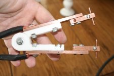
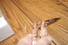
I'm busy redesigning the power supply for my machine to make it cheaper and use less components and this weekend I used my CNC machine and made a Hand held attachment for the welder....here are the photo's

tabwelderhand.jpgtabwelderhand2.jpg


Great thread!

I've been eyeing the v1 build of this on LED hacks for a while, and after I bought materials for it today at a local swap meet, and went back to the site, I noticed the other Tab Welder II and found the link back to this thread on good 'ol E:S and realized it was RLT. Please forgive my ignorance and stupid questions, I am learning a lot of the concepts around this as I go, I am planning on starting with a crude implementation and and I don't want to fry myself.

I got these two massive 100v 82000 μF caps (above) at the swap meet today for $10 each. I''m feeling kinda stupid because I was so excited that they were 100v, I misread the μF and thought they said 820000 μF, so instead of 1.6 F I have 0.164 F :oops: . I'll try to find the same guy next month and buy the rest of what he has and parallel them into something higher.

While my ultimate goal is to weld a few kwh of a123 1.1ah cells into high-amp packs, right now I just want to get a feel for CD welding so I know what the limitations are. I had a fantasy of welding copper strap to the cells to carry some serious amps, but it sounds like that might be a challenge.

I saw RLT's "Higher V weld" page on LED hacks, so I am thinking that if I use a higher V I could actually do something with the piddly 164,000 μF I have now. RLT you said over 25v you were meling the electrodes, at <25v to you think I could make some decent welds with what I have right now? Of should I just get some of the 'professional' electrodes you mentioned and try it at higher volts?

The only SCDs I found at the swap meet were these little 35a ones sitting on the caps - they were a buck each so I bought them anyhow, I'd reckon they would fry if I tried to use them on this so I need to pick up something better, I have to go re-read this thread for detail.

-JD

PS would this copper strap help folks in paralleling caps? Instead of hammering tubing, I've bought 1/2" and 1" strap from metalelectric and used it on EVs and Ebikes:

http://cgi.ebay.com/ws/eBayISAPI.dll?ViewItem&item=220361898185
 
I'm trying to source a local company that can do tab welding before I try to build my own, but so far am not having any luck... I've tried the local tool repair shop, but no joy. Anyone have any tips on what sort of company might do this kind of thing.

Also... if anyone here built a simple tab welder and just don't want or need it any more let me know 'cause I might buy it off you! I'm really bad with building my own stuff, but need to weld together a couple hundred 18650s.
 
Got all the parts to build the "$100 CD welder", but I'm confused about one last thing.. the SCR I got has two leads coming out the red and what the manual calls a "white gate" only. According to the ledhack.com page the negative from the gate switch battery is connected to the big bolt end of the SCR and it looks like his only has a single lead coming out...

http://www.ledhacks.com/power/CDweldPost/SCRcuL.jpg

So I was going to hook my red positive(?) lead to gate switch battery + and "white gate" lead to gate switch battery -, but wanted to check here first to see if that was incorrect and that I should still connect negative gate battery to the bolt as per the ledhacks page? Thanks for any tips and sorry for my ignorance! :oops:

dscn6098.jpg

View attachment st230spb.pdf
 
Well I got impatient and proceeded as is ( :mrgreen: ) charged the cap and... nothing... so either a) I'm wired wrong or I think more likely is b) I don't have enough voltage from a single cell to trigger the gate... if I'm deciphering the PDF product sheet correctly is looks like I need minimum 1.8v to trigger. Have to wire 2s I guess and try again.
 
Well... figured it out... white is positive, red is negative.. obviously... :roll: ...a cap can seem to be reversed briefly without damage :oops: and this is going to take lots of practice... :lol:

EDIT: *sigh* After practicing for a couple hours tonight I can say with some conviction that if you follow the $100 Tab Welder instructions to the letter you will not be able to use this with konions. Seems I can get Duracell "C"s and "D"s and NiCads from toolpacks etc. to weld very well, but the konions didn't get any penetration... at least on the positive side... negative side actually seems doable and with about 4-6 welds holds extremely well. I think the problem is that I have a wide enough tab material that it covers the positive side completely so I can't do 1 on/1 off so can't get in deep enough... I have to do 2 probes on the tab material on the + side and that just isn't cutting it. On the negative side I can do 1 on/1 off and it sparks/welds pretty well. Since I'm going to be pumping 2kw+ through this pack though I need the extra wide tabbing... so...

Ordered a $10 16v 2a DC power supply from ebay that I'm hoping will make the difference otherwise... no joy at 13.2v. I'm about $130 into this project so far.

Having said all that this setup works extremely well overall for basic cells... the hardest part for me was grinding down the 4 gauge tips into nice, smooth pencil like shape! :mrgreen:
 
Just curious I see your cap there, but I have no reference, what size cap is that? If it's a car cap you got to know that it's probably way over rated. Also how much current are you dumping into the gate? Because those gates like to have quite a bit of current to open quickly, and this is the goal dump out as much current in short a time as possible. I'm working on my version 3.0 right now after failing with 2 versions, because my so called 2F cap was maybe 0.6F lol.
Now I have the 2 main caps out of hybrid capacitors, total capacitance of the main caps together, 1.22F to 1.58F depending on the measuring method. discharge over a known resistor from 11V to 5V and timing it gave me a measurement of 1.22F (but there is self discharge that frak's that up so should be a bit more) the 1RC method gave me a calculated measurement of 1.58F (but there the lead acid may have droped a little bit in voltage during charging so that frak's that up a bit towards lower capacitance) So I figure anywhere from 1.3F to 1.5F for the two in parallel :D . I figure I will have fairly decent welds with this thing somewhere around 13V to 15V. I'm gonna build a circuit which can cut off the charging current with fairly decent accuracy and charge this cap with about 17V worth of juice, so I get up to 13V to 15 V faster, but I cannot exceed 16V charge in the cap so I gotta build a nice little circuit.
Anyway's test your cap's capacitance by using two multimeters (I only got one working one right now :() measure the time to charge it to 1RC and then you'll know how much you were ripped off lol.
my .02
terramir
 
Hi,

pwbset said:
I think the problem is that I have a wide enough tab material that it covers the positive side completely so I can't do 1 on/1 off so can't get in deep enough... I have to do 2 probes on the tab material on the + side and that just isn't cutting it. On the negative side I can do 1 on/1 off and it sparks/welds pretty well. Since I'm going to be pumping 2kw+ through this pack though I need the extra wide tabbing... so...

Could you fold the tab into an L shape (narrower), weld it, and then flatten the L?
 
oatnet said:
Great thread!
I got these two massive 100v 82000 μF caps (above) at the swap meet today for $10 each. I''m feeling kinda stupid because I was so excited that they were 100v, I misread the μF and thought they said 820000 μF, so instead of 1.6 F I have 0.164 F :oops: . I'll try to find the same guy next month and buy the rest of what he has and parallel them into something higher.
I saw RLT's "Higher V weld" page on LED hacks, so I am thinking that if I use a higher V I could actually do something with the piddly 164,000 μF I have now. RLT you said over 25v you were meling the electrodes, at <25v to you think I could make some decent welds with what I have right now? Of should I just get some of the 'professional' electrodes you mentioned and try it at higher volts?

Well gotta tell ya at 35V to 40V you'd be getting about the same energy than most of the regular tab welders here have, namly 100Ws to 131Ws


oatnet said:
The only SCDs I found at the swap meet were these little 35a ones sitting on the caps - they were a buck each so I bought them anyhow, I'd reckon they would fry if I tried to use them on this so I need to pick up something better, I have to go re-read this thread for detail.

Hope these are scr's but anyway 35 amps means usually that they can handle higher peaks, however the gate rise time maybe a problem Look for A/us or A/ms my 2000V 350A continous I D=420/550A one can handle a rise of 250A/us and a peak of 8500A for 10ms@ 25C and 7500A for 10ms at 130C , you could try to parallel the two scr's ergo trigger them at the same time, but watch that you keep everything equal, (i.e. the protection resistors for the gate, wire length etc.) likely hood is your gonna fry em eventually rather sooner than later but they were a buck each so what the hey. know that the contact resistance will probably limit all our current to about 250A @ 15V is good to know however with your higher voltage you'll have higher currents at the same resistance.

oatnet said:
-JD

PS would this copper strap help folks in paralleling caps? Instead of hammering tubing, I've bought 1/2" and 1" strap from metalelectric and used it on EVs and Ebikes:

http://cgi.ebay.com/ws/eBayISAPI.dll?ViewItem&item=220361898185
that should work fine but I'd do two or three layers LOL
 
MitchJi said:
Could you fold the tab into an L shape (narrower), weld it, and then flatten the L?

Mitch! Always with the useful ideas! :D Gonna run out and try that and will report.

@terramir - it's the exact same cap as the tutorial... the Volfen-something-or-other so I know it's not the best, but I don't think that's the issue. I think if I can get a 1 on/1off weld and up to 16v I'll be okay. I'll try your multi-multi-meter trick and stuff too.. thanks for the suggestion!
 
Ahh what a difference a volt makes! I've got some DC wall warts laying about and thought.. hmm.. turns out one of the "9v 300mA" puts out 14.45v so I hooked it up to my capacitor and 'lo and behold I'm actually getting some penetration on the konion positive end now!! Where 13.2v didn't cut it at all 14.45v is close! These 4 welds pulled off somewhat easily... with pliers... progress! I have no doubt that once my 16v power supply arrives I'll be in business. Total investment for this CD welder around $140... not too shabby!

 
Hi,
pwbset said:
Ahh what a difference a volt makes! I've got some DC wall warts laying about and thought.. hmm.. turns out one of the "9v 300mA" puts out 14.45v so I hooked it up to my capacitor and 'lo and behold I'm actually getting some penetration on the konion positive end now!! Where 13.2v didn't cut it at all 14.45v is close! These 4 welds pulled off somewhat easily... with pliers... progress! I have no doubt that once my 16v power supply arrives I'll be in business. Total investment for this CD welder around $140... not too shabby!

Great news :D 8) :!:
 
MitchJi said:
Great news :D 8) :!:

Thanks Mitch... it gets better... just found an old Linksys router wall wart at work that is putting out 16.8v @ 1A! That should provide the perfect konion + weld about every 8-9 seconds. Now soon we'll see if 4 welds/cell can handle 2,500 watts sustained. :mrgreen: If you take out the $20 Walmart charger from the HOW-TO and just scrounge the house/office for the right wall wart that makes this the "~$80 CD tab welder". :D

Worth noting for konion fans that the Makita V cells have 2 little welds/cell while the Makita VTs have 4 and the VTs in the Bosch fatpacks have far superior/thicker welds than any of the Makita stuff, which is probably why a single fatpack can dump 1,200 watts sustained 'til LVC with no issues at all. :shock:
 
pwbset said:
Ahh what a difference a volt makes! I've got some DC wall warts laying about and thought.. hmm.. turns out one of the "9v 300mA" puts out 14.45v so I hooked it up to my capacitor and 'lo and behold I'm actually getting some penetration on the konion positive end now!! Where 13.2v didn't cut it at all 14.45v is close! These 4 welds pulled off somewhat easily... with pliers... progress! I have no doubt that once my 16v power supply arrives I'll be in business. Total investment for this CD welder around $140... not too shabby!
Yes the stored energy formula in a cap is E= (C*V^2)/2 so yes a volt means quite a jump :wink: cause of the squared thingy. :D
Let's assume you got a 1F (real not crappy car rated) Cap there
E= (1*13.2^2)/2= 87.12 Joules (Ws)
Now
E=(1*14.45^2)/2=104.401 Joules (Ws)
Now with 16V
E= (1*16^2)/2=128 Joules (Ws)
so you see a Volt can make quite a bit of difference, but you can also hit a resistance wall so check the following suggestions:

Three comments:
A. how thick and long is your wiring leading to the probes?
If you can cut down on the resistance you'll be way better off cause the lower the resistance the greater current can flow at once! Ohm's law definetly applies to capacitive spot welders. :!:
B. ever check out that cap for actual capacitance?
If your below a real farad you might want to invest in a second one for version 2 of your welder, gotta tell ya you'll have twice the power availible and you might want to invest in a ajustable psu then.
C. you'll probably not need 16V more like 14.8V to 15.3V or something to get good welds on those konion welds, be careful you don't wanna go overboard with the power, welding through cells :twisted: would be a waste and a bitch.


Good luck and cheers on your progress :D
terramir
 
pwbset said:
just found an old Linksys router wall wart at work that is putting out 16.8v @ 1A! That should provide the perfect konion + weld about every 8-9 seconds. Worth noting for konion fans that the Makita V cells have 2 little welds/cell while the Makita VTs have 4 and the VTs in the Bosch fatpacks have far superior/thicker welds than any of the Makita stuff, which is probably why a single fatpack can dump 1,200 watts sustained 'til LVC with no issues at all. :shock:


:shock: :twisted: :!: Be careful 16.8V Could be above the max that cap can handle ppl have blown their caps that way, sometimes it just vents and still works albeit at a bit reduced capacity. Don't exceed the 16V limit unless you want to risk your cap.
On the weld issue you got to remember if you did the weld right you also have a whole surface contacting as well so the amount of welds is not as important if you did it right, more likely you'll burn through to narrow tabs if it can't handle the current, than losing the welds.

Be aware and GL :D
terramir
 
Thanks for all the great info terramir! I'm using the exact same "1.5f" Volfenhag cap that the how-to uses, which they said 16v continuous and 20v surge and it looks like he used it at 18v without issue (though he didn't go into it). I'm hoping 16.8v is within a tolerable overage range and honestly my Radio Crap multi-meter reads high anyway I'm finding so we'll see what my good multi-meter at home says tonight. I'll post photos of the carnage if it vents etc. :shock: The konions + side is really thick and is detached off the top of the cell can anyway so I don't think it'll punch through. Good to know about the 2 vs 4 weld thing.. maybe after practice I'll get it dialed in and need less welds. I think I need to "sharpen" my electrode pencils a bit more also... they are pretty blunt. Anyway.. thanks again! Love trying to digest the technicals you throw out there... :)
 
pwbset said:
Thanks for all the great info terramir! I'm using the exact same "1.5f" Volfenhag cap that the how-to uses, which they said 16v continuous and 20v surge and it looks like he used it at 18v without issue (though he didn't go into it). I'm hoping 16.8v is within a tolerable overage range and honestly my Radio Crap multi-meter reads high anyway I'm finding so we'll see what my good multi-meter at home says tonight. I'll post photos of the carnage if it vents etc. :shock: The konions + side is really thick and is detached off the top of the cell can anyway so I don't think it'll punch through. Good to know about the 2 vs 4 weld thing.. maybe after practice I'll get it dialed in and need less welds. I think I need to "sharpen" my electrode pencils a bit more also... they are pretty blunt. Anyway.. thanks again! Love trying to digest the technicals you throw out there... :)

Well let's get technical again:
Assuming the "how-to's" estimate is correct with 16.8V you'll have an charge stored in the capacitor of 16.8 Coulumbs and an energy of 141.12 joules or Ws. this should be more than enough for a regular weld A123 cells on the other hand are aluminum so for those it might not do, however if you followed the first how to your probably using 10 gauge wire, the probes are 4 gauge wire. Now if I assume you have at least 8 feet around your looking at .008ohms of resistance at 12 V and 250 amps your looking at almost halving the voltage that actaully goes in the weld. however if you used 4gauge speaker wire (comes in nice colors you can get it at a car stereo store) you'll quarter that resistance and the voltage drop will almost drop to a 1/4 as well.
Mind you this is assuming the following a perfect capacitor (esr=0) total circuit resistance of about .6 ohms (which is realistic if you press hard) and a thyristor that has no voltage drop whatsoever.
But there is something to be said about bulking up the wires. every little bit helps in our situation there is a reason capacitive spotwelders are so expensive.
GL with your project, but I'd say you should at least bulk up the wires.
terramir
 
Back
Top