Build your own CD battery tab welder for about $100.00+-

Jeremy Harris said:
........... a shower of sparks, as I lowered the electrodes without realising the thyristor was already turned on..........

I've done that several times. Fortunately, I never blew electronic components... Just big holes in whatever I touched the electrodes to. UNfortunately, I did blow holes all the way through the battery can a few times, especially when I was using the dual pulse, higher voltage setup., resulting in worrisome moments and the loss of a few fairly expensive batteries. Mine were most often caused by my hands not knowing what my foot was doing. Now, if I don't hear my fans spinning, I know that I've still got my foot switch pressed.
 
Oh, I forgot to update you on the .01 thick nickel sheet from Admiral... It works GREAT at 16 to 18 volts.... At least with my 6.5F of car audio caps (5F+1.5F parallel).

I welded a ˜1/2 inch wide strip of it to a small steel bar with just 4 spotwelds and couldn't rip it apart with a pair of Schollhorn parallel pliers (they are about the best gripping pliers you can get, short of Vise Grips) on the strip and the bar in my other hand, pulling with all my arm strength.

Finished off my most recent battery pack with the .01 attaching the 8Ga wire to the + and - ends of the pack, and I'll never worry about tearing it off accidentally as I have with the .005 stuff even doubled up.

So... If you are tabbing any big batteries, (like the Headways, etc.), it is worth considering if you are looking for both mechanical strength and high current capacity.
 
Good tip about the 10 thou Admiral sheet, I wish it were cheaper to get it over here in the UK. I ended up using 0.15mm (about 6 thou) sheet as it was all I could get easily. I've doubled it up in the high current areas and made bolt-on terminals by soldering two bits of nickel sheet with a bit of copper sheet in between. I left the nickel sheet strips longer than the copper, so I could bend them out and then weld it to the battery tabs already welded in place.

Thankfully my pack (64 off Headway cells) is now welded up and ready to go. Tomorrows task is to build the battery rack to hold all these cells.

Jeremy
 
Jeremy Harris said:
......made bolt-on terminals by soldering two bits of nickel sheet with a bit .....

Oh, Thanks;
That reminds me of something I 'invented' a couple of months ago, and intended to report here...
I haven't actually used it to build a pack yet, but it works very well in basic testing. I am planning to build most of MY Headways into 2P4S (12V/20A) sub-packs and make them easily reconfigurable, so I'll be doing this to the pack +&- ends:
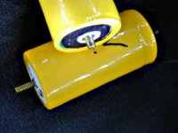
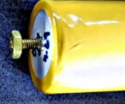
st1.jpg
st2.jpg

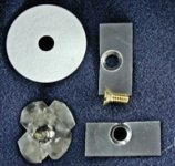
Here is how I did it:
st3.jpg
Drill a hole in your nickel tabbing material just big enough for your screw to fit through... I'm using a #8 screw here, but have used #6 and #10 as well. (For my test, I was sloppy and got off center on all of them... When it is 'for real' I'll use a drill press and a vise or a jig)

Then I used a screw countersink to carve a cavity in a piece of aluminum block to shape the nickel to the screw head. (I'll go take a photo of that and post it, if anyone really needs me to.)

Then silver solder the brass screws inside the formed hole. (Not the silver bearing low temp solder most of you are familiar with... I used jewelers silver 'solder' which is actually more accurately called silver brazing because it is a 1200°F process.) You could probably use regular or silver bearing electrical solder, if you are careful, but if you do your CD spot welds over or near where there is low temp solder, it tends to 'squirt out the sides, contaminate your electrodes, and/or vaporize and poison your lungs.

Now that I think about it, if you built a jig to hold them and shaped your electrodes just right, , you could probably use your CD welder to weld the nickel directly to the screw and eliminate the soldering completely.
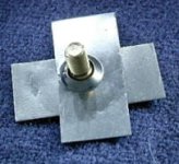
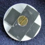
st4.jpgst5.jpg

Then use your CD welder to attach the assembly to your battery, just like you would regular tabs.

That white disk in the photos is a very stiff 1/32" thick 'Fiber washer' I got off ebay:
http://cgi.ebay.com/ws/eBayISAPI.dll?ViewItem&item=380049774779
It fits perfectly on the ends of my 32650 LiIon cells... A little bit small for Headways , but the eBay Guy http://stores.ebay.com/RuBBeR-HoUsE will get any size you want.

You could get away with not using the fiber washer, but I really like it for two reasons: Not only does it add mechanical strength, but it provides great electrical insulation safety.... I don't know how many times I was working around the positive end of these batteries with a pair of pliers or other metal tool, and kind of crushed through the heatshrink and/or paper insulation and shorted the battery right at where the negative can crimps over the positive terminal disk.

Use a little glue to stick the fiber washer to the ends of the battery over the screw.
Then put some heatshrink over the whole thing, and you are 'good to go':
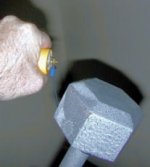
st6.jpg

Thats a fifteen pound (7 Kilo) weight hanging from the screw terminal... I can even jiggle it up and down, and it holds just fine, so this is a decently strong assembly and should stand up to at least a normal level of real-world abuse.

Of course If I had been willing to wait until Headway gets their screw terminals batteries into production, this would have been a moot exercise, but the basic idea is adaptable to just about any battery from sub-C on up... Maybe even "A" diameter flat top NiMHs, with #4 screws and a sharp point on the welder electrodes....

When I do this for my Headway sub-assemblies, I'll stamp out round disks of the .01" thick nickel sheet from Admiral instead of using the rectangular tabs like I did above... I bet that with decent welds of that stuff, the terminals will be good for 50 pounds.... Probably pull the positive terminal disk out of the crimp before the screw and nickel base will tear off.
 
That is a really, really neat idea - I wish I'd thought of it!

Thanks for sharing.

Jeremy
 
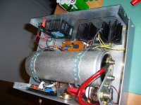
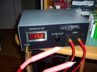
Here is mine! 8)

I use a one car audio 2 farads 20V capacitors, a SCR coming from a surplus electronic store and a small circuit comtrolling the pulse width.

The red display indicate the capacitor actual voltage.

The box is made of aluminium with some labels made with CNC machining.

I also have some thungsten 1/4" rod not shown on the picture.

The results are great.. but i will ned to learn with experience hor to get the best weld :wink:
 

Attachments

  • P1040852_1024x768.jpg
    P1040852_1024x768.jpg
    169.6 KB · Views: 2,920
  • P1040854_1024x768.jpg
    P1040854_1024x768.jpg
    115.9 KB · Views: 2,882
Hey Dr.

really KEWL!! very nice looking project. that is a slick looking case.

i don't see an AC power source. what are you using to power your Variable power supply? is there an external stepdown transformer?

how about a schematic of the timing circuit? any possibility of a peek?

rick

again - WOW!
 
I think, Rick, he runs it off of one of those 100 megawatt packs he salvaged from Sony!!! :)
otherDoc
 
Hey Doc (Bass); Great to see you built yourself one.

When (if) you get the time, how about posting more info on your setup... Like, especially, your timing circuit, etc . (Hint, Hint)

How are your welds? with only 2F (compared to my *nominal* 6.5F), your capacitor must have a much lower ESR than mine, if you are getting solid welds.... If I squint my eyes and look at your last photo, it appears that you are using 15.8V... which is only 1.2V more than my current setup uses.
 
hi I'm actually gonna get into this game myself :p Got a car cap (2F hope it's at least 1.5) a 2000V 210 thyristor (off eBay has actually two thyristors inside) and a footswitch. Planning on using my 12V net (which is somewhere from 15V to 11.5V depending on time of day and charge level :p. The things I have not figured out yet:
A. how to trigger the thyristor thinking about using a 7805 based supply with a transistor that get's triggered when I hit the foot switch.
B. how to disconnect the current from charging the cap so it will reset itself, was thinking the same voltage that triggers the thyristor would also trigger a relay, however I think I should use a small cap there behind a transistor as a switch to keep the relay open for just a short while longer. I dunno exactly yet, but I was thinking that would help so the scr will reset itself.
I really need to read up more on using a transistor as a switch. Also I will probably use a 2N2222 in conjunction with some other transistor to make the relay circuit that way I can use 5V to switch on the thyristor but 12V on the relay.
well any hints would be appriciated.
terramir
 
Hi Terramir; Glad you joined up here. (sorry you had so much trouble getting in contact with me directly)

It is just as well you did join up, as I couldn't have answered those questions anyway.

Maybe some of the other guys can.
 
Hi,

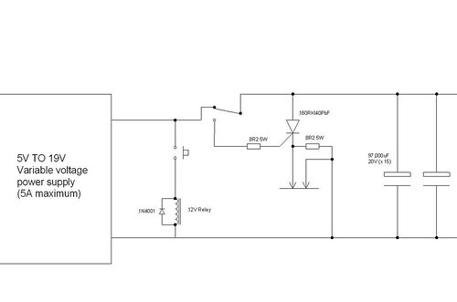
You don't need anything fancy to trigger the thyristor, just a switch and a current limiting resistor from your main supply. Take a look at the circuit I posted for mine, a page or two back - you can see that I just trigger my thyristor from the charge on the capacitor, it works a treat.

The same goes for cutting off the charge whilst the thyristor is on, if you look at my circuit you can see that the trigger relay switches the supply off for as long as the push button is pressed.

There's no need for any fancy circuits, just a trigger button, changeover contact relay and current limiting resistor are all teh parts you need to trigger the thyristor reliably and not short out your supply with it.

Hope this helps,

Jeremy
 
I goty a question though my thyristor semikron 210/20E (actually there are 2 in a package have three main current connectors and 4 connectors for the steering the schematic on the package looks like this: here's a link to a picture http://theelectrostore.com/shopsite...kkt-210-20e-skkt21020e-scr-semikron-used.html got it for less than half that price on e-bay :D anyway my big question is what is up with number 7 and number 4? number 5 and 6 look like the wire comming into any thyristor but I really ask myself what the other ones are there for :?
terramir
 
I guess you already know that you only need to use one of the two thyristors in that package, but one looks as if it will do fine, as it has a peak current rating of over 8000 amps at the sort of temperature and pulse width a CD welder works at.

I've drawn you a circuit diagram, using this thyristor and using a changeover relay and push button for charge and "fire" control. Hopefully it should be self-explanatory. The relay in the diagram is shown in the non-activated position, with the normally closed contact charging the capacitor.

Good luck!

Jeremy
 
Okies any car relay should work there right? I got a bunch of those laying around somewhere! Also one more question if I can't find that particular diode (although I think that should be in one of the bunch of old fried PSU's I got laying around) will any standard rectifying diode do? Also I decided to use old ball point pencases as insulation for the contacts in my battery tab welder held in place with shrinkwrap you guys think that will do as handles for the electrodes? also I am making the electrode tips out of 5 guage solid copper wire, they sold it as 4 guage at the Home depot but measured it's 5 guage will that do?
terramir
 
Pretty much any old diode will do - it's not really essential - you could leave it out, all it does is limit the spikes from the relay to be a little bit kinder on the push switch contacts. It'll work fine without it.

The relay needs to be a changeover type, one that switches a connection from one terminal to another, rather then just on and off. Some car relays are changeover types and would be ideal. They often have a small diagram on the side showing the connections.

I'm in metric land, so can't visualise what 5 gauge looks like. If it's AWG, then it seems to be about 4.6mm diameter, which is probably just about OK. My electrodes are 6.35mm (1/4") diameter and work OK. It helps to have the thickest cables you can connecting them - I'm using some two parallel runs of 16 sq mm (about 6g, I think) per electrode.

Jeremy
 
help one question to all anyone know how to get the multimeter off a 2.0F absoluteUSA car cap, it'sn the red one but I dun think that makes any difference. Any help would be appriciated
terramir
 
Jeremy, I looked at that circuit again since I'm gonna be assmbeling it tommowow And I noticed something your using the scr on the positive rail. I read something on the forum of the guy that built that original under 100 buck welder and they said that the scr should be on the negative firing rail. Does it actually make a difference? this is the quote I'm talking about
Philpem wrote:
Update 07Sep2005 18:04 BST:

For those who have been asking, no that photo isn't one of the welder in its current form. The current welder switches on the low side (SCR cathode wired to ground), and has the SCR directly mounted onto the middle of the bus bar.

The reason the current shot up when I moved the SCR to the low side is because the current in the SCR gate has to find a path to ground to trigger the SCR. In the original welder, that current had to go through a metre of welding cable, a piece of nickel and two electrodes. Now it only has to go through a lump of thick copper. A lower resistance path to ground equals a sharper turn-on pulse, which means more current goes into the weld. Thanks to Ben Weaver (bjw105) for pointing this out.

I revised the schematic to reflect that also one other problem I don't have a 68 ohm 3 watt resistor the best I can come up with is paralleling 7 470 ohm 1/4 resistors to come up with a 1 3/4 watt 67ohm resistor all my big watt resistors I have handy right now are in the less than 10ohm range putting those in series would be a mess would those 7 in parallel be enough? Also thinking about adding a 3ohm 5W resistor to the charging side since I'll be charging this Capacitor from a 12V (well most days it's pretty full so 14.4 to 15V solar bank)to limit the charging current going through my Car lighter socket that is attached to my 12V net. I know that will delay the recharge time some, however not more than a second or three. Eventually I might regulate the circuit further and add two more caps another car cap and some small super caps in a parallel series configuration to be the initial pulse but at the current time this will have to do. What do you think about my modifications?
terramir
 

Attachments

  • welder.pdf
    29.9 KB · Views: 632
That configuration will work just as well as the way I made mine; mine triggers fine and gives more than enough welding current, probably because I'm using the full capacitor voltage to trigger the thyristor, rather than a small battery.

I only put the thyristor in the "feed" to the electrodes so that I could have one electrode permanently grounded. This just made it easier to build the lever operated rig, as I only needed to make sure that one electrode was insulated from the metalwork. It also made the thing a bit safer, as there were then no live connections anywhere that were exposed (the live side of the thyristor and capacitor bank are inside the wooden base box).

Sorry, I've just realised I made a mistake with that diagram I drew for you. I meant it to be the same as this one, but using your thyristor (please ignore the other 8.2 ohm resistor, I later removed it as it didn't wholly do what I wanted, which was to act as a safety discharge for the capacitors, without needing to make a weld):

2618106641_75312e878c.jpg


The gate resistor should have been 8.2 ohms, 5 watts. I'm really sorry about the mistake, I hope it doesn't cause too many headaches.

The gate resistor isn't that fussy, it just needs to be sized to give enough gate current to trigger the thyristor quickly (they like a fair bit of gate current, around an amp or so, to switch fast). The power rating is probably a bit of an overkill, I just happened to have a big resistor around that did the job. In theory, the resistor needs to dissipate nearly 15 watts initially, when it has about 11 or 12 volts across it, but this very quickly drops as the capacitors discharge. My 5 watt resistor barely gets warm, even after an hour or so of welding packs up, so I think I could easily have got away with maybe a 1 or 2 watt resistor.

If you can get a resistor of over a watt with a value of around 8 to 15 ohms then I think it'd be fine.

Sorry again for the error.

Jeremy
 
well Hmm I think I could parallel 11 100 ohm 1/4 W resistors for that LOL anyways, Thanks for your help so far I'll see how it's working tommorow afternoon hehe. Actually after I'm done with this first stage, I just thought of a different project, although that project depends on a factor I cannot calculate right now :p, Making a mini portable Tab welder out of 10 super caps in a 2x5 configuration = 11V 5 farads which would be enough to store 300 joules, the question is how fast those things give off their charge :p gotta get a hold of a few of those and do some tests LOL but first build my regular cap spot welder :p.
The catch about my welder is that those Cap specs are over rated, I dun think My cap should use more than 15V and well I dun think it's really 2F (it's a car cap) I will do a charge timed test tommorow. I.e. how fast it takes to charge it over a 3 ohm resistor should give me some indication on how much it really stores
terramir
 
You're right about those car audio capacitor specs, they tend to be exaggerated a bit. I was lucky, in that I managed to get 15 off, 97,000uF, 20V computer power supply capacitors via eBay at a knock down price (less than even the cheapest car audio capacitor). Although I only have 1.455F, I can go to 20V safely, plus these capacitors have a very low ESR, so they dump current fast with few losses.

Keep us posted on how it works out.

Jeremy
 
Hmmm all that work and not a thing, it's wierd but I don't seem to be able to weld any of the tab material. :evil: the only spark I got is when the probs accidently touched each other. I dunno but maybe the the cap is too weak or the scr is broken. Or just maybe the power i'm taking to switch the scr is screwing with the weld. I went up to like 14.7 V even if this thing is overrated by 100% and it's only 1 farad (2farad car cap) I should be able to get a weld at 14.7V gawd even if it was .7 farad it should still have enough power :S
I dunno but maybe the resistors themselves are also causing the scr to be too weak any hint before I go back to the drawing board. I have an lm317 handy also a 7805 so I could switch the scr independantly of this darn relay I dunno any simple modifications I could make I already know I'm gonna have to take this apart but I would like to avoid losing power to triggering the scr.
Help
terramir
 
update if I hit the foot switch more than once it does sort of stick, however it peels off real real easy
I scanned in the piece of nickel tabbing I'm using I just thing I'm gonna have to go with a more advanced circuit or buy another cap (well gonna upgrade next month anyway (buy another one like it) but I wanna weld now :(. So gonna have to go with a more advanced circuit.
Help anyone got one that is simple enough though.
terramir
I added attachments of what I was thinking of changing and the picture of the welds that didn't work
 

Attachments

  • welder2_0.pdf
    31.6 KB · Views: 900
  • welder2_0a.pdf
    34.2 KB · Views: 756
  • weld_1st_try.jpg
    55 KB · Views: 1,954
well I got some help from my electronics group and there telling me I should switch my SCR and my relay with the foot switch, but use a resistor 120 ohm's 1W and a timing cap 470 uf to delay the switching of the scr till the relay breaks contact. :D If my relay goes up in smoke :lol: :p that means I should replace the cap with a bigger value LOL. Anyway I will post my final circuit with credit to the guy that helped as soon as I tried it out. probably will take me till tommorow afternoon to finish this soldering job. (well today need to sleep for a few hours though.
terramir
 
Back
Top