oldusedbear said:
Well - - My easily derailed train of thought involved a mixture of what both of you are saying. I was thinking of a substantial (15 Amp or so) AC relay on the input side of my battery charger. Using a 5 amp NC microswitch to open the relay contacts when the foot pedal is pushed. When I just LOOK at a microswitch, I can never believe it will sustain the current rating claimed.
You might want to go with a car relay setup instead of an AC relay the low voltages that we use are unlikely to need the arc protection that an Ac relay uses, however the current protection of a 40amp 12V car relay is quite a bit better, and those relay's are cheaper as well
")
I'd recommend bosch relays there quite sturdy and easy to find at autozone, napa, pepboys, kragen or whatever their called at your neck of the woods.
oldusedbear said:
As a future improvement (in place of the foot switch), I was considering a small working platform on which the battery pack would sit, and within the platform I'd have the microswitches. Then figured I could support the platform with changeable springs that would determine the electrode pressure when the second microswitch closed. Spring strength to be chosen/adjusted to optimize the weld. For starters tho, I figured it might be best to minimize the number of variables by using the foot switch.
That might be a good idea if your gonna make several packs and using a spring to trigger the microswitch means that you can use several types of batteries with the setup. But for now get the thing setup and use a footswitch so you can learn.
oldusedbear said:
Thanks for the SCR source info, Terramir. That looks like a substantial component. Maybe even if you can't do the Siamese separation thing, you at least have a backup if you toast half of it?
True true the way it's wired I could use either one but not both together
but I dun think I'll be able to fry this part unless I go crazy on the voltage. the contact resistance and the coil I'm gonna use prevents that from happening.
oldusedbear said:
Now if someone can recommend an appropriate brand of audio capacitor or capacitors? I'm guessing that 3 Farads would be ample but could sure use advice on that too!
I wish someone would answer you there, But I can tell you the best approach might be to go with car caps and go local, find a car stereo place that offers various brands, buy one test the capacity complain try another brand. All brands will be significantly lower than the advertized capacity. Stay away from the hybrid capacitors though they have super caps inside and while the advertized esr will be low it would only apply to max the first farad (i.e. the main cap).
oldusedbear said:
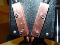
After considerable rumination, and staring at my electrode mounting system, I'm going to try the thing of separating the mount so each electrode can move independently. Then, enlarge the holes for the mounting screws, and use a little bitty O ring between the screw and the mount - - Hoping this will give me just a little bit of "give" that will allow the tip pressure to equalize. If that doesn't work, I can easily morph the design to a more conventional spring loaded setup. No question but what regular springs would afford a greater range of movement.
Springs are availible at hardware stores, and usually the best selection will be at the mom and pop stores, how depot and such usually don't have a very good selection in springs.
Hope this helps
terramir