Build your own CD battery tab welder for about $100.00+-

16V. I can go high as I like, I'm using a proper benchtop supply, but the cap starts to do some odd things about about 16.5 or 17 volts.

And yep, it's a crap 6 farad cap - it measured 0.7 farad. I stoopidly bought it before reading through all 50+ pages of this thread. At least my SCR is good (2300 amps peak).

I have a monster cap on the way, and I'll sell the rubbish cap on on ebay. I've got it bubble wrapped, and kept the packaging. I can sell is as "never been installed". But it's good enough for testing while I get the circuit done and some nickel shim.

I'll pick up another monster cap if one is not enough.

(Assuming the new monster caps are as good as the old ones? Any ideas?)


Thanks

Mark
 
I've tested lots of Monster and Rockford 1F caps. All have been very good. They appear to be made by the same company, but are different (Rockfords weigh more). The Rockfords have very little unit to unit differences. If you sort through some Monster caps you can find units exceed their specified values (more capacitance/lower ESR). My welder currently has 3 Monster caps installed. The combo measures 3.65F and less than 250 micro ohms ESR!

Your crapassator almost certainly has a crappy ESR...

Is that 2300 amp SCR the continuous or pulse rating? My welder can easily dump 20,000 amps. A good 1F cap in a properly designed welder can produce over 6000 amps...
 
No, that's the pulse rating. It's as big or bigger than all the ones I found discussed so far..

It's one of those big 3 terminal jobs. About 100mm long.

It was about the biggest I could find!


http://pdf1.alldatasheet.com/datasheet-pdf/view/102547/SANREX/PK90FG120.html
 
I found some NTE devices on Ebay that were 550A/9000A rated... posted the link here and they went bye-bye in a hurry.

Hard to say how an SCR will hold up in this application. They aren't really spec'd for what awaits them :twisted:
 
I got a second hand monster cap, and it measures approximately 1.2 farads. So you are right there texaspyro.

With the Monster cap and the crap cap in parallel I can just weld the Headway Nickel Strips back onto dead Headway cells, and yep, Admiral steel can help me out with some Nickel Shim. Right again. (Single Monster cap on it's own is not enough BTW.)


I'd really like another decent capacitor. Has anyone got one for sale? I'm scouring ebay, but there's only craptacitors or very expensive Rockfords at the moment.


And my SCR appears to be holding up fine. The calc my EE mate did based on the CRO trace was about 1500 amps, we are going to check if beefing the (heavy) wire and connections up further will help.

Cheers

Mark
 
One more question, anyone know why Nickel is used as a tab material in preference to Brass? I've never seen brass used in a welded pack.

Brass is a better conductor (depending on grade).

Does it spot weld ok?
 
Surfing ebay today, found this :

http://cgi.ebay.com/Dental-Spot-Welder-BRAND-NEW-/380324188927?pt=LH_DefaultDomain_0&hash=item588d1692ff

Not so much of a deal at 300$ but if a used one came up for cheap, would this do ? ( I admit complete ignorance on these things, so sorry if this is a total dumb question )
 
Not any real info to tell what it is/does. Rated at 400W. My welder kicks out 400,000+ watts.
 
Need help, I am in the process of building the tab welder as featured on this link (http://www.ledhacks.com/power/tab_welder%20ii.htm). I have it all assembled and ready to go. My problem is that I cannot get my scr (GE 9E 2n1913) to close when the scr is wired to my 3.5F capacitor. When I test the scr when it is disconnected from the capacitor, I am able to get scr to close using the 1.5v "D" battery, micro switch, and 48" long 22awg wire. A picture of the scr is found at the bottom right hand of the page at: http://www.surplussales.com/Semiconductors/SemiC-SCR.html

I wired up the low voltage scr's wire in a loop. White wire from the scr is hooked to the + positive + post of a single 1.5v "D" battery; from the - negitive - post of the "D" battery is a thin gage wire (22awg) running to a micro-switch that I have mounted to one of the electrodes that is operated by my finger; from the micro switch, the wire returns back to the scr's small red wire. The total length of this circuit is approximately 4'.

Could the wire gauge (22awg) be too small for the control circuit loop? As stated before, when I test the scr when it is disconnected from the capacitor, it closes, but when it is hooked to the capacitor (charged by the power supply or dischaged), it doesn't close. Is some how the capacitor robbing the low voltage or is the wire gauge to small to carry the mili-amps needed to close the scr gate?

My componets are as follows:
* SCR: GE 9E 2N1913
* Stinger cables: 2awg, 40" long
* SCR low voltage gate control: 22awg, 48" long
* XCP-350 Capacitor 3.5F
* Power Supply: Mastech HY3006D
* Electrodes: 4awg solid copper wire, 11" long

Thank you in advance for any help concerning this topic.
 
You probably need a higher gate drive voltage... attached is a schematic for a reasonable SCR welder. The gate is driven off the capacitor. The SCR is in the negative lead. If your charger power supply is a current limited lab supply, replace the 5 ohm-20W resistor with a wire. Increase the 10 ohm-3W resistor to around 33 ohms. This circuit shows a dual SCR, only half the package (pins 1,3, and 6) is actually used.

Add a warning beeper across the probes. It will beep if you don't fully discharge the caps in a weld and the SCR stays on. Otherwise you will get a nice sparkly surprise when the probes touch the next weld.

That is a pretty wimpy SCR, but should not be a problem since your cap is crap. I measured an XCP1 which was supposed to be a 1.5F cap... it was 0.1F You will be lucky to be able to weld anything with it.


View attachment welder.pdf
 
Thank you Texaspyro for the information. I will work with the new design and see what I am able to do.
 
Trying to decide whether to try building one of these $100 DIY tab welders. Can anyone who has built one tell me if you really can put it together for about the $100 I see quoted? Considering time is money, is it worth the effort? The alternative would be to buy a Sunstone welder for like $3500. I like the Sunstone because it features a double-pulse weld that can easily be adjusted for best weld depending on materials.
 
I think that you will find that the Sunstone units are more than $3500... for one that did what I wanted, the price for a dual-pulse welder was around $20K. I built my own and it is far better than any commercial unit plus I can make it do whatever I want since I designed the hardware and wrote the code.

Yes, you can build a SCR welder for $100... if your junk box is rather well populated. Most likely cost is around $200 if you already have an adjustable voltage/current limited power supply. The key to a working welder is getting properly rated capacitors and SCR. I can help with the first item... I have a few sets of Rockford caps available.
 
Thanks! Let me study up on this thread for a while and I might take you up on those caps. The quote I got from Sunstone was under $4k for the welding unit and another $150 for the hand-held electrodes. I think it was this one. http://sunstonespotwelders.com/spot-welder-160ws-dual-pulse.php
 
That Sunstone is 160 watt-seconds. Fine for small batteries and tabs (like AA size) My welder spits out over 750 watt-seconds. You need that much power if you are going to be welding beefy material, copper, etc to he-man batteries.
 
I wonder if you could attach hand-held electrodes to one of these cheap spot welders and use it to weld tabs.
http://www.harborfreight.com/115-volt-spot-welder-45689.html?utm_medium=cse&utm_source=pricegrabber&mr:referralID=2d6f06f7-703d-11e0-9770-001b2166becc
 
Hello all, I would like to start off by thanking everyone who has been participating in this discussion. I have read every comment on every one of the 53 pages so far. and I am impressed with how dedicated this community has been in brainstorming and solving these problems. As it works out I just started purchasing my supplies.

So far a 1-60v 3 amp power supply(I know a little wimpy for amps but reasonably priced... and I am not in a huge rush anyways.)

three 110,000uf 75v caps, which I plan on expanding on with a number of bays of 80v or 100v smallish caps. I would like to go up to 60v with the system... which as you say is in the deadly range. If I was planning on working at range what would you suggest as a maximum bank size? I was hoping to work up to about a farad that I can shuffle around into separate pulses. Also is there an advantage to more then two pulses? could one use three or four for better penetration?

I believe I will be receiving an adequate scr in the mail soon too.

My goal is to be able to tack sterling silver, which I know will be a real challenge.

Now it comes to my request. I have a number of ideas that I would like to be able to run by you all, feel free to shoot them down hard, but if you do I would really like some solid information as to why. I hope that is fair.

So here goes.

First off I am a little afraid to set up the FET system for pulse control. I have very little practical circuitry experience, but lots of build experience. So I came up with an idea, could you use an electromagnet next to a series of reed switches for a crude pulse control, say first controls the charging relay then the subsequent reed switches control the gates on a series of scrs? I was figuring if the reed switches were in this configuration the electromagnetic field would activate the nearest fastest because the magnetic force is stronger the closer to the magnet. Am I at all on to something here? it seems the dual pulse single reed switch design seems to preform fairly well, and if all the reed switches were actuated by the same field pulse there wouldn't be nearly the same delay that he was experiencing.

Another thing that I am thinking may be a terrible idea... or possibly a good one... it just popped into my head... could you have a double capacitor bank(ie double your rated load with caps rated well over for voltage) and then use a voltage sensing transistor circuit to push the remaining voltage to small to be useful in welding into the second cap bank, there by closing the scr, flip the power supply to the second bay charge it back to usable voltage and pulse again back into the first bank? I know you would loose most of your power in the weld, but I would figure you would see major advantages in weld repeatability rates.

And I can only think of one more thing, besides expense would a small platinum pad embedded in a sturdy chunk of fine silver be good electrodes for welding silver? I know others are talking about molybdenum. Would that be a better choice?

I fear by now people are starting to figure out that I have far to little electrical knowledge... Ah well at least I am in the company of masters.

Oh I thought of one last thing. I had heard something about a pulse transformer mentioned very briefly. Someone stated that it is a major undertaking to design one, just wondering if anyone knew anything, maybe a link I can research from?

Thank you again and in advance for your help. It has been a pleasure lurking on the forum the last few weeks.
 
Ah one more thing, can I have multiple banks of caps go through separate scrs to the same bus bar then to electrodes then to ground or will there be a chance of burning out a scr from the amperage of an adjacent one fired before/after? Hope that question doesn't give me away as to much of a noob. just needed to ask.
 
Wow, I guess I read a little to much without asking the questions... now I feel like I am playing catch up... Would anyone know if it would be worth investing in silver plated wire for the welding circuit? I just found some on ebay and though it could be nice. $25 for 5 feet of 6gu or $25 for 1 foot of 4ga. I figured I could run 2 or three of the 6gu and avoid the high price per foot of the 4ga.
 
burnmetal said:
Ah one more thing, can I have multiple banks of caps go through separate scrs to the same bus bar then to electrodes then to ground or will there be a chance of burning out a scr from the amperage of an adjacent one fired before/after? Hope that question doesn't give me away as to much of a noob. just needed to ask.

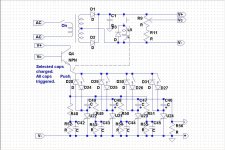
I had the same idea. See attachment.

CD Welder Concept Schematic.jpg

Something like this should probably work. Each SCR supports only one cap and it's maximum current, select more than one cap for greater pulse width. The rheostat represents a variable peak voltage charging circuit. The charge circuit part of this is too simple, only good to show most basic functionality. Control portion should be good. The SPST switches select which caps are charged, but all caps are triggered when the button is pushed, the ones with no charge just don't do anything. R48-51 are the trigger resistors for the SCRs, value depends on the SCR characteristics. SCRs do not all have to be the same. R52-55, and C42-45 are for noise/false trigger suppression. R56 is to ground the caps, also can limit charge current, value probably around 1 ohm or so. I haven't built this yet, but I'm working on it. Using disk SCRs, which have potential mounting challenges. Takes a while for one with limited machine shop capabilities.

Dave
 
dbird -

To mount the puck scr, in the spirit of this forum(cheap and easy) what about finding some seriously overbuilt heatsinks, then just putting some over built, over sized hose clamps to apply the force, a little insulation to prevent arcing of the current, or dare I say seriously overbuilt zip ties? I don't know if you could reliably exert enough force with zip ties or not, I don't know much about the necessarily clamping pressure needed. But I am sure a good dose of heavy hose clamps strategically placed and properly insulated would do the job admirably.

Sort of an scr sandwich in a two layer deli wrapper

Wood or phenolic for the insulation. One cheap one professional.

Your circuit seems good. I wish I had enough of a background to know what values and bits a pieces to use, but I know there is enough info in the posts to figure them out. So as I understand it looks like pulse width is only controlled by the over all capacitance rating of the selected capacitors? Does that offer solid control?

I was playing with the idea of putting a resistor, tiny capacitor, and a voltage reliant transistor circuit in line to time the delay between each scr activating. with a variable capacitor, or selector switch attached to a scaled capacitor bank a person could fine tune the pulse delay. Again I have no idea what numbers would be involved or if the idea of this circuit is to bulky or could be handled better with different parts. Or if this type of circuit would be responsive enough to do the job at all.
 
I was also playing with the idea of including the option to power different banks of caps with different power supplies, it would nice to make a very versatile, simple design robust enough to be able to experiment with. I would then be able to set up some tables for usability and perhaps a few more recipes for the other noobs to follow.

I guess the rules are simple enough 1 true farad @ 12 v, through the largest scr over 100v100amp, tabs nickle well enough, more is better, more sophisticated is better, neither is necessary. But a few simple solid improvements in the $100 welder would be great, and obtainable.

I am sure we can come up with a simple pulse width method that anyone can set up and use with success.

Don't get me wrong, FET control is amazing. Really amazing. But I for one don't have the skills or the confidence to attempt such a feat, and I am sure there are a few others here that are in the same boat. Just thought of yet another question, can a FET circuit be controlled without a micro controller?

The 555 circuit looked promising as it didn't require programming. Major plus for most people. I can program feebly in pascal and c. Nither will help me with this project.

just my $0.02.
 
burnmetal said:
dbird -
So as I understand it looks like pulse width is only controlled by the over all capacitance rating of the selected capacitors? Does that offer solid control?

Yes to both questions. The concept circuit can be expanded with more cap/SCRs for finer control if wanted. I've not made any welds yet, so it's not clear to me how much one can swap voltage for pulse width. Also, this concept only allows for full discharge of all charged caps for each weld. No pulse turn-off using SCRs. That can be done(SCR turn-off), but at these current levels and overall circuit impedance levels it's hard to do.

burnmetal said:
I was playing with the idea of putting a resistor, tiny capacitor, and a voltage reliant transistor circuit in line to time the delay between each scr activating. with a variable capacitor, or selector switch attached to a scaled capacitor bank a person could fine tune the pulse delay. Again I have no idea what numbers would be involved or if the idea of this circuit is to bulky or could be handled better with different parts. Or if this type of circuit would be responsive enough to do the job at all.

You are on your own here. I haven't played yet with trying to delay/multi-pulse the circuit. That's getting way to far ahead for an experimental get-up that hasn't yet even been "bread boarded".

burnmetal said:
I was also playing with the idea of including the option to power different banks of caps with different power supplies, it would nice to make a very versatile, simple design robust enough to be able to experiment with. I would then be able to set up some tables for usability and perhaps a few more recipes for the other noobs to follow.

My caps have different max voltage capacities. Initially, I will characterize/measure each in-circuit for total resistance, capacitance, and max voltage. Then, to operate at different voltages, all I have to do is monitor charging with a volt meter and select only those caps that will go to the target voltage. Using DPDT switches, I can add some circuitry to stop charging at the selected cap's max voltage. This for safety of course.

burnmetal said:
Just thought of yet another question, can a FET circuit be controlled without a micro controller?

Definitely. No doubt about it.
 
Just forget about doing dual pulse welding with SCRs. It will perform far worse than single pulse!

For dual pulse to work, you need to be able to adjust the energy in the first pulse to the point where it causes the weld to be just below the point where the metal sticks. The first pulse is only to blow away any crap on the metal surfaces,

If you cause the metal to stick, the second pulse will not be as effective. You will have welded some of the joint together and this will create a conductive path that will lower the weld resistance to the point where the second pulse cannot produce enough heat to properly bond the metal. Plus the second pulse needs to be timed properly in relation to the first pulse. An SCR welder does not provide the control and finesse to do this. For this same reason multi-pulse welds are useless.

For welding highly conductive metals like silver you should use molybdenum electrodes. And avoid tungsten electrodes... they just don't work well. They tend to blow away the weld metal.
 
Back
Top