Build your own CD battery tab welder for about $100.00+-

thanx for that link, awesome read.
it's new to everyone cuz he's still building it right now in real time.
started it only little over a month ago.

so now i get it.
why these audio caps don't measure up.
not a lot of farads in a piece of rock.
and they say there's no such thing as a freemason conspiracy.
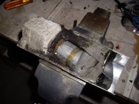
fig. 39.jpg

This makes me feel rather angry and ripped-off. How can a company market a product that performs at one sixth of its stated rating?

I measured the capacitance of both Boss capacitors at about 0.24 Farads each (even lower than when they were first installed). With my trusty hacksaw I carefully cut the top off one. It was immediately apparent that the pitch encapsulation inside the can had locally melted and that the liquid insulation/dielectric was sloshing about above the pitch seal

Interestingly the actual capacitive element was not central to the case but had tilted in the pitch during manufacture - almost coming in contact with the aluminium case. Its overall dimensions were just 41 mm diameter by 75 mm long (in a case 76 mm in diameter by 215 mm long). There was some type of refractory block in the base of the capacitor that smelled strongly of ammonia and dulled my hack saw blade at the speed of light. See Figure 39.
Anyone that buys one of these capacitors might reasonably ask why they are paying for 1/3 brick, 1/3 pitch, and somewhat less than 1/3 under specification capacitor!
 
so now i get it.
why these audio caps don't measure up.

Contents may have settled during shipping. :evil:
 
Wow, what a scam. It should be tossed right back at the company's window.
 
Really bad isn't it. Guess that's why texaspyro has been measuring certain units as crapacitors. Should of set his test gear to old brick mode. Reminds me of a scart splitter box I got years ago, always felt like a quality bit of kit, had call to remove the cover one day only to find a 6"x6"x1/4" lump of steel in there doing nothing other than adding the feel of quality. Shocking really.
 
I did pass the info on to some class action lawyers... they seemed rather interested at first and spent quite a bit researching things. I don't know if anything well become of it.
 
deleted a bunch.

update: I got it working well with just 2 IXYS 230n20t fets. I got decent welds with only 1ms pulses, I think.. 70ms apart? whatever was noted in above posts..

IT WORKED for a little... while the TC4422 driver was alive. IT burnt up. I don't think I have it wired right.. I think it's cause I'm running arduino off the same supply that's charging the caps.. and I'm running the fet driver off the same supply! I'm going to try isolating everything when my next TC4422 comes in. by the way, I'm giving everything 15V. The caps are 15V rated.

The only other issue maybe you guys can help me solve is that the caps are draining after I charge them.. Which would indicate they are draining through the fets or maybe the driver. (which are on the positive side of the caps).

3 Caps are Sprague 300000MFD. I hope that their close proximity and gobs of copper bussing will make them useful, even at .9F. IN case you're wondering, the electrodes are insulated by kapton. Sometimes when I take it apart in this prototype phase, I'll have to redo the kapton cause I tear it while taking the blocks out.. but there is no mechanical action that would wear the kapton and short the copper blocks/frame, but I suppose that wouldn't have too ill of a consequence.
6480388243_8738d21f30_z.jpg
 
It really makes me wonder what goes into a good welder... especially for driving the fets. I saw the above diagram and found it fairly complicated. Maybe overcomplicated.. maybe the right amount-- I have no idea what I'm doing. I just used the arduino, the TC4422, some fets, and some relays. Here are some more pics... though these were early stage crude states...

I did everything from scratch.. down to the remachining of a single completely worn electrodes I got from batteries plus. Machined the aluminum base from some scrap.. machined down the 80/20 for better Z action. It has an adjustable hand lever you pull down. shot 10 speed chain and bike gears.. machined inners for the gear to fit 22mm skate bearings which I just had.

Not sure how safe it is to have caps upside down resting on the arm.. but direct pressure is on the edges of the caps, not the terminals. Pressure pad is under the 1/4" wood... right under the electrodes.

6567845547_c5bbc3e56d_z.jpg

6567753639_3753af631a_z.jpg

6567754043_2e8c71810e_z.jpg

again.. pretty early stage.
6567807913_c96efc8059_z.jpg

6567807471_e94e5a63f4_z.jpg
 
On my welder I have only one input supply that everything runs off of. It is nominally a 19V, 400 watt supply, but can be anything from around 7V to 30V. I like 19V since there is no way you can overvolt the 20V capaitor bank. The welder runs great off of a 12V battery. I have even run it off a tiny wall wart (takes a while to charge the caps).

However, there is a series isolation diode from the main power input to a separate filter cap (10,000 uF) that feeds a 12V (or 15V) regulator that supplies the gate drives. There is a 5V switching regulator off of that 12V rail for the CPU and other logic. That 10000 uF cap can keep the CPU up and running for several seconds so even if the main caps are fully drained, it never loses power or gate drives.
 
hillzofvalp said:
Which isolation diode do you think i need? Do I put the cap positive after the diode which feeds the driver? And ground the other cap lead to primary supply ground?

Just about any power diode will work fine. I used a generic 1A Schottky diode, but silicon will work fine (like the 1N400x series). Input of diode (side with triangle symbol) goes to the main power input. Output of diode (the side with the bar symbol) goes to the cap positive. Cap negative goes to primary supply ground. Voila, the cap is now a voltage isolated supply for the micro and gate drives. It should hold up a few seconds (depending upon the load) after the main supply voltage drops.


But I do have to mention that if you are asking this sort of question, you probably should not yet be building something as technically demanding as a high power CD welder. There are MANY, MUCH more difficult and technical things involved and nasty, smokey, sparky, expensive, fiery things await.
 
I hear ya. Like i sais, i do not know what im doing, but i think i know enough for this project. EE is a field im beginning to study, and I am treating this project with the utmost caution. In the end, though, I need to weld my batteries.. And a simple, not very well thought out welder circuitry design will have to suffice in my concrete basement. Besides, I enjoy a winter fireworks show ;). Thanks for your input.
 
Does your weld held allow the positive and negative probes to move independently? If they are fixed then you probably won't be getting consistent, repeatable pressures on each electrode. One of the subtle keys to getting good welds is the ability to provide consistent, controllable pressure on each electrode. The electrodes will wear at different rates and getting fixed electrodes to maintain their relative position is just about impossible.

Also, the pressure for the positive and negative electrodes should be independently controllable since the heating at the positive and negative electrodes is different (due to things like the thermoelectric Seebeck/Peltier effect. You can compensate for the difference by adjusting the electrode pressures.
 
Yes.. They're conventionally mounted. Pictures are deceiving cause I took one bad electrode and made two new ones half the original length. There is a set screw for each.. And lots of contact with copper blocks. It will be possible for me to indicate the electrode variance off of multiple machined points on the main structure..
 
Hi All,

I read all 57 pages of this debate. Some very interesting reading - and amazing welders. Thought I'd try a low-$$ build - although not welding for batteries. I need to join .060" dia stainless rod for artwork I'd like to make. Someone suggested that I might need approx 250 watts/sec to weld this stuff.

There were some positive reviews on the Volfenhag ZX-3 3.0. Thought I'd try a pair.

Problem # 1. I just received my crap-acitors today. I charged them up and down to 5v, measuring charge and discharge times. Apparently, the Volfenhag ZX-3 3.0 capacitors on ebay right now are only in the 0.5-0.6 farad range. The ones I got don't match the photo - have heat-shrunk-on wrappers, they could be anything.

http://cgi.ebay.com/ws/eBayISAPI.dll?ViewItem&item=140613672686

Should I put more than 5v for capacitance testing...?

Any recommended sources for more reasonable capacitors?
 
I've tested several ZX-3's and they were all around 1.0F (useable, but not what they advertised). Their ESR was around 1.7 milliohms (50-70% higher that what a really good cap measures) I would try testing with a larger voltage swing. It's less likely to induce timing and self-discharge errors.

The sure fire good, honest, blow your SCR to smithereens caps are the Rockford Fosgate and Monster Cable 1F caps I've tested over 100 of them. (PM me if you need some). Avoid the Rockford 2F cap. It is a "hybrid" capacitor that is not suitable for welding.
 
I rigged it all together and tried some material.

I can join .060" wire fairly well @ 21v - but worry the caps will blow. 50% more umph would be very helpful - then I could get something done. If the capacitance is so far off - likely the 24v volt rating is too. What happens when caps are over-volted? :)

I will PM you re: caps. The back of the packaging says they are rated for 45,000,000 mf - but the shell does packaging does not look like the website photo... I'm thinking these are fake.
 
4.5F is a lot. If you wanted, you could get a second and put them in series for higher voltages... so as long as your within 0-1V of their rated voltage.. for example two 15V caps in series would give you 30V, but you don't want to risk overvolting them if they were out of balance.. so charging them to 28-29V would be safer.

Alternatively you could discharge them both before you charge them up.. or create a relay network that charges each one individually.
 
<put them in series for higher voltages>

I recommend not doing this. It is relatively easy to get the charging voltages correct/balanced. But, not so easy for the discharging voltages. When discharging, the caps with the least capacitance will discharge faster. Then when the smallest cap is at zero volts, a larger cap in the series stack will still be discharging and reverse the charge on the smallest cap. Not good!

But, if you are using FETs and keeping the caps well charged between pulses, this won't be such a problem. Even then though, design care should be taken to make sure the power off discharge does not reverse bias any of the stack.

Dave
 
dbird said:
<put them in series for higher voltages>

I recommend not doing this. It is relatively easy to get the charging voltages correct/balanced. But, not so easy for the discharging voltages.

Balancing resistors across the caps work well. I have several Maxwell ultracapacitor modules that have 6 350F 2.5V caps in series. (58F at 15V) They use balancing resistors across each cap. They also have a version with active balancing circuitry if the drain from the balancing resistors is an issue.

Going to 20+ volts on a CD welder is probably not a good idea for most applications. Better to go with more farads at a lower voltage. Once you get over three real farads at 20V, simple pulse welders start putting too much energy into the weld in too short a time period. You really need to rethink your welding strategy (along the lines of inverted DC welding).

I did rig a couple of those Maxwell Ultacapacitors into a 29F, 30V version of my welder, but it is awfully scary since it can do 13,000+ watt seconds. The ESR of the caps limits the weld current to around 1250 amps. Draining the caps or lowering the voltage is rather hard on the discharge resistor.
 
hillzofvalp said:
can you make a guess at whether my Sprague 3"x9" .3F caps have low ESR? I don't have a scope to test, and my multimeter is rather cheap.

Nope, ESR is way too dependent upon how the caps were built. It could be just about anything. I would guess that their ESR is low, but probably not spectacular. Their probable originally intended application (providing power-fail holdup time in a computer power supply) did not require it to be all that low.

You need some rather specialized test equipment to do measure it properly, and at least a scope to half-ass it. A multimeter will not tell you anything.
 
K.

I have 2000mfd worth of capacitance for the filter bank you spoke of in the above posts for my welder. However, I don't think I need more than the diode... since I don't weld every 5 seconds (more like every 8-10). I'm just trying to remove load going through the driver when it is not triggered.. which I believe is just a diode between main psu + and TC4422 Input pins. Everything can have the same ground as long as this diode is present, correcT? Maybe the main caps were draining intermittently because of Fet and/or driver leakage.. Let me upload a schematic

When I turn it off without draining the caps, it will trigger my relay board as pulses... kind of strange.
 
Here we are. Here's a really nasty diagram that's more simple than it my appear. everything with same ground.

6609755307_f4c50d5811_z.jpg


I added a pull down resistor. For some reason there is a 0-300mV fluctuation (15V when caps connected to positive lead and NOT grounded) at the weld head in the "OFF" State. I was surprised when I went to town on a cell and I got a nice loud pop. not sure if it was the arc or a fet.. :( but when powered down I don't have gate-source continuity.
 
I had it working a little bit. the first one sounded awesome. Popping a lot from wrong electrode subtleties. Worked well! (I hope my fets are okay.. they're not stuck on).

But then it stopped working. For some reason my Vgs only ramps up to 230mV when the TC4422 driver is triggered manually with 5V.

the electrodes have a voltage corresponding to the 2000mfd bank for powering driver. ?
 
Back
Top