Burned yellow butt splice connector

rudivb

100 mW
Joined
Sep 5, 2023
Messages
40
Location
France
I was troubleshooting my DIY BBSHD 52v bike running @33amp max.

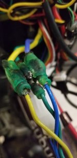
Came across these burned butt connectors on the main and I also take a small current for accessories from here.
(This was not the main issue, but happy I came across it)

Before I've always been using those heat shrink with solder connectors, but after reading about crimping, it seemed to be a better choice.
The connection seems strong and solid, nothing came loose.
These yellow butts are just cheap ones I found, is there any difference in buying more expensive ones?
Any thoughts?

IMG20240413134813.jpg

IMG20240413134823.jpg
IMG20240413135807.jpg
 
You don’t always get what you pay for, but if it’s cheap, you usually do.
Often you just pay for a brand name or because somebody imports from China and charges you a premium.
All these crimp butt connectors look the same to me, so I thought I could just get the cheapest.

But if you mean by what you are saying that I should get some more expensive ones from the hardware store because of quality differences, I'm all up for it.
 
My thoughts after being co-owner of a company doing wiring on big rigs.

Never saw a properly soldered connection fail out. Have seen thousands of crimps, done right, have issue.
+1000!

A good solder joint + hot melt adhesive lined heat shrink will be better than the wire it is in.
 
My thoughts after being co-owner of a company doing wiring on big rigs.

Never saw a properly soldered connection fail out. Have seen thousands of crimps, done right, have issue.
I need to get proper solder equipment and learn to solder at some point with this hobby. :)
 
Ther is a japanese chap that does video's on soldering on youtube. He uses either a very dry translator, or a very good robo voice. In any case, My son loves his vids, and it has improved his understanding, evidently trying to watch me was giving him fits because.. I can't slow the video down to show him what I am doing, and with fine circuits you have seconds to complete from wetting the tip to pulling away from a completed job...

It is a good skill to have, it ain't like we are gonna suddenly stop using electrons.
 
Often you just pay for a brand name or because somebody imports from China and charges you a premium.
All these crimp butt connectors look the same to me, so I thought I could just get the cheapest.
I solder everything, but other folks on this forum run huge currents and sear by crimps. I’ve also seen cases like yours posted here often. Most of thos cheap connectors will accept a certain wire size, but the connectors have bottlenecks, using thinner or narrower copper that can’t conduct the current. Happens with cheap soldered connectors too.
If I were using crimp connectors, I wouldn’t go down to Home Depot. I’d buy from a place where I’d know what I was getting, and for the right application.
I just got a box with different connectors, but no awg, no amp rating, there is 0 info on it.
Will be looking for some proper connectors with the ratings I need!
 
Last edited:
Having the right crimping tool is probably more important than the brand of fittings. Crimped connections can be prone to corrosion and fail over time. Personally, I like to solder things.
 
Back when I frequented car forums, endless arguments about solder vs crimps. Navy vets always had the last word when they said the big cables on ships were crimped, Well, of course. How you going to solder wire that is 1/2" diameter.

For the above power connection, I like crimps with solder inside. Holds up better for vibration.
 
I like crimps with solder inside
Is that like a butt crimp with solder inside, so after you crimp, you heat it up with a heat gun and the solder melts?


I have been using those shrink solder things you heat up, which I haven't really had any issues with:
Kg
 
I find 5.5mm bullet connectors to work very well for my 30 amp 10AWG silicone wiring setups. Have not had anything close to failure with them.
 
Most of the problems with crimped connectors are that the wrong tool is used to create the crimp, or insufficient force is used, or the crimp barrel itself is not hard enough to hold the shape, or it's used on too small a wire, etc.

This causes too high a resistance at the connection, so you end up with this type of failure.

If it's bad enough, you can even have arcing inside the joint that can cause a fire from the heating. (this happens inside a lot of crappy fuse holders)

It also allows easy entrance of humidity or moisture into the joint that can oxidize / corrode it and make it even worse.

If you want to see if your crimper / barrel works, take the plastic off the outside of one and crimp it onto a spare bit of the wire you are using. Do this right on the end of the wire so the crimp itself is where you can see it thru the end of the barrel (not just the loose wire strands beyond the crimp). If the resulting crimp doesn't look essentially like a single large strand of wire, without airgaps in it or between it and the barrel, it's not a good crimp. You can do a google image search for "what does a good crimp look like", or a bad crimp, and see the difference. (there are a number of crimper / crimping threads and posts with details).


You can solder a bad crimp to "fix" it; it won't be as good as a good crimp, but better than a bad one. You must use a method that heats up *all* the metal of the crimp high enough to thoroughly melt the solder and bond it to all the strands and the barrel, preferably wicking it into all the air gaps.

You can also just completely do it by soldering, there are many forms of solderable butt splice without using a barrel, where the mechanical connection provides most of the conductivity and joint strength, and solder is there to secure it and keep moisture/etc out, and improve conductivity a bit.

There are solderable barrels with a hole in the center to feed and wick the solder thru to ensure it gets everywhere in the joint. (any poorly-mechanically-joined solder joint that isn't fully soldered is about as bad as a bad crimp). The solderable barrels don't provide any mechanical joining, so the conductivity depends on the solder to work.


The problem most people have with soldering is they don't use a high enough power iron, so it cannot put enough heat into the connection to actually melt and wick the solder in. For most wires on a typical ebike, 40-60w is enough, and using a large chisel tip (pinky finger sized) helps a lot with thicker wires. (there are a lot of "which soldering iron" posts and threads that cover this in detail).
 
I've been happy with all the various joining techniques as long as they're well done. That said, I had an intermittent loss of power issue recently that I traced down to a ring terminal on one of my battery leads. Movement and vibration had broken the coarse wire strands where they exited the crimp fitting, but the battery's packaging was keeping the busted-off wire ends in contact with each other almost all the time. Resistance was high, so there was heat damage which gradually increased resistance and the number of episodes of open circuit.

I suspect that the failure would not have happened as soon or at all if I had soldered the ring terminal, or if I had used fine stranded wire.
 
I suspect that the failure would not have happened as soon or at all if I had soldered the ring terminal, or if I had used fine stranded wire.
The fine strands would probably have helped, but soldering can actually make that kind of problem worse, when it wicks into the strands out beyond the support provided by whatever the mounting method is. Then the vibration or bending, etc., stresses them at the end of hte wicked area, and does the same thing you saw with the crimp.

If the break is between two supported areas, and the wicking is across the entire unsupported span and into the areas on either side, it might make it stiff enough to prevent any movement and thus any breakage, but that's not usually what happens. :(
 
The fine strands would probably have helped, but soldering can actually make that kind of problem worse, when it wicks into the strands out beyond the support provided by whatever the mounting method is. Then the vibration or bending, etc., stresses them at the end of hte wicked area, and does the same thing you saw with the crimp.

Yes, but I haven't witnessed that failure mode yet. And I have given it a lot of opportunity. All my early e-bikes used solder only or crimp plus solder, because I didn't have legit crimping tools so I used vises, crappy crimp/strip tools etc. when crimps were involved.

I wouldn't rely on gimpy crimps with solder backup anymore, but that hasn't let me down so far. This latest failure wasn't even an old connection with lots of miles, nor one that got articulated much (it was tucked away inside the battery case). On the other hand I think it was a vise crimp and not a proper crimp. 10ga wires fwiw.
 
Yes, but I haven't witnessed that failure mode yet. And I have given it a lot of opportunity. All my early e-bikes used solder only or crimp plus solder, because I didn't have legit crimping tools so I used vises, crappy crimp/strip tools etc. when crimps were involved.
Ah. I have seen it in a variety of technology over the years, mostly on factory circuit boards with individual small-gauge unsupported wires coming from them, but a few larger wires on power electronics (mostly factory-built audio amps, a couple of user-built ham radio sets, some UPS units).

I've also seen it on my own ebike stuff (primarily on early CrazyBike2 versions and earlier attempted builds when I was in a hurry to finish or fix things).
 
....... Then the vibration or bending, etc., stresses them at the end of hte wicked area, and does the same thing you saw with the crimp......

:(
Several layers of shrink tubing from the connector to an inch or so beyond the spot where the solder wicked into strands will suppress the movement that might cause the strands to fail. I have done that with good success. It might take a modest amount of thought and planning if the shrink tubing needs to be slipped over the wire before soldering.
 
Is the yellow connector constructed of inexpensive 'tinned' plated steel tubing that is plastic coated ( magnetic )?
Because: You made a circuit carrying 35? AMPSs through a high resistance point made of steel.
I believe when the AMP company invented butt connectors they were well made in the USA clear through plastic and silver plated.
 
It wasn’t necessarily poor junction between cable and terminal.

There’s little by way of spring retention with bullet connectors, they’re essentially just friction fit, so loosen every time they’re reconnected, and suffer from wiggling or strain. They require strain relief at either side of the junction.
 
I just came across a similar issue, repaired with solder and spread the wires apart for more air separation.

Attached image is of the before, I caught it before it got sparky, soldered the joint and added speed holes to the casing for more air flow.
 

Attachments

  • 20240414_105418.jpg
    20240414_105418.jpg
    811.1 KB · Views: 6
Is the yellow connector constructed of inexpensive 'tinned' plated steel tubing that is plastic coated ( magnetic )?
Because: You made a circuit carrying 35? AMPSs through a high resistance point made of steel.
I believe when the AMP company invented butt connectors they were well made in the USA clear through plastic and silver plated.
I'm not an expert, but it's probably indeed inexpensive material, as it were like the cheapest connectors you can find, won't be using these again I guess.
 
Back
Top