C Cab Hot Rod Power Advice

I believe this module (7 cells) is a Gen 2.
That 55.6-volt reading is only a few minutes old.
Hi again Ed,………happy new year !👍
To be clear,…. Leaf battery packs are assembled from multiple “modules”, each containing 2 x 3.6 v cells.
So each of those modules is 7.2 v nominal.
Your pack seems to be 7 of those 7.2 v modules, or 14 cells, giving a nominal voltage of 50.4 volts.
But, other than some restriction built in by Tecdirectclub, ..(most likely the BMS ?),..there is no reason why that pack should not support a much higher output current.
Maybe have a talk with the vendor ?
PS,..if you are not using that pack regularly,..just storing it,..it would be benificial to discharge it a little down close to its 50.0v nominal , to prevent premature pack aging.
Storage of cells at near full capacity (voltage) is not good for longevity.
 
Last edited:
Hi again Ed,………happy new year !👍
To be clear,…. Leaf battery packs are assembled from multiple “modules”, each containing 2 x 3.6 v cells.
So each of those modules is 7.2 v nominal.
Your pack seems to be 7 of those 7.2 v modules, or 14 cells, giving a nominal voltage of 50.4 volts.
But, other than some restriction built in by Tecdirectclub, ..(most likely the BMS ?),..there is no reason why that pack should not support a much higher output current.
Maybe have a talk with the vendor ?
PS,..if you are not using that pack regularly,..just storing it,..it would be benificial to discharge it a little down close to its 50.0v nominal , to prevent premature pack aging.
Storage of cells at near full capacity (voltage) is not good for longevity.
My brain fog keeps me from using the correct terminology in many life endeavors. Thanks for enlightening me on the subject. It's been discharged down once since I bought it. so I'll find a use and work it for a while. I have a DC to AC 3000-watt inverter, so I can hook it up to a 1500-watt heater and see it as a test...???

Today's progress

Yesterday I/we placed the body back on the frame. I was able to see how much clearance was left after welding in the seat brace at the lower back. I ended up with about 1/4" between the brace and the drive chain. I will lift the body about an inch to regain the lost space. An additional benefit is, I can see further down the road.🤓

I've discarded the dual-seat idea in favor of a button-tufted bench and back.

Not much but it's a beginning.
As I stated previously, I have to spend considerable time visualizing the design and then how to make it work.
Anyway, the seat bottom board is cut and a foam board temple is ready for tracing onto a plywood seat back.

The weight keeps climbing, so I hope I'm getting near the top. The 'last?' heavy item, if I choose to use it, will be the rear wood insert. I'm seriously thinking of open or perforated metal.

DSCN5723.JPG
 
The weight keeps climbing, so I hope I'm getting near the top. The 'last?' heavy item, if I choose to use it, will be the rear wood insert. I'm seriously thinking of open or perforated metal.
FWIW, I used the lightest "dogwood" fence planks I could find at Lowes when I built the back end of SB Cruiser. It's lighter than metal would've been to do the same job, and doens't turn the back into an easybake oven in the sun. ;)
 
FWIW, I used the lightest "dogwood" fence planks I could find at Lowes when I built the back end of SB Cruiser. It's lighter than metal would've been to do the same job, and doens't turn the back into an easybake oven in the sun. ;)
That's a thoughtful suggestion. Today I took a step backward and ground down/apart the seat/back supports. Why? you ask. Well, the answer my friend lies at the bottom under all the other brainy minutia.

I sat in the mock-up and decided I wasn't going to have room for my posterior and the elements of the design. Using the 'KISS method, I searched my stash of wood and other forgotten artifacts. Waste not - want not...right? Found some wood that will do the trick, and not waste a trip to the big box store. Basic modification entails lengthening the seat bottom and moving the backboard rearward about 3 inches. So goodbye to having access to a storage area behind the seats.

Tomorrow I will put tonight's brain-storming into effect and make new, lighter, better, stronger?, seat supports. As usual photographic evidence of the crime scene will follow.

A request of sorts

I want to attach carriage lights to the side of the body. So I'm on a quest to find a pair of lights no more than 12 inches long. Old vintage is best but finding the right style and price together is important. Priority is on style.

I'm scouring the internet and have found some, but they haven't been a pair, were way too expensive, or not suitable.
Maybe there is a source near someone reading this that would help locate such a treasure.

Examples below.
The slender style is what I'm most interested. (bottom URL) But anything longer than 12 inches (16,17, 18, etc) is too long.

Price ranges from about 0-$100 US dollars. Up to $150.00 only for pristine condition in the right style.

vintage carriage set lamps - Google Search
 
Last edited:
I've seen carriage-style wall lamps for inside and outside houses (my porch lights are actually like that) but the way the ones I've seen are made, I don't think any of them would be up to the stresses of being on a moving vehicle for very long, without some rebuilding.

If you're willing to make your own, it should be relatively simple to make these two styles
1736143504209.png
1736143596109.png
Some of the ohters look much more complicated to make.
 
Hello from sunny California...NOT

Thanks for your reply amberwolf

It's story time. Grab a cup of Joe, sit back, and let me take you on a short journey of woe—gloom, a broom, and rid of a foe.

This early morn, we awaken to a little storm. It's wet, cloudy, and dark with gloom, yet I let that not dampen thoughts of what must be done this early morn.

DSCN5725.JPG


First, we must pickup tools, and find where they room, then on to pushing a broom.

DSCN5726.JPG

My shop must be a dust/dirt magnet. What you see is but a short few days since the last sweeping. I must close off the top skylight/vents, in hopes that will help. You can imagine what the rest of the shop is always like, dusty, gritty, not to mention how hard it is to keep the project clean-ish.

With the floor swept and the tools returned to their rightful spot, I had a thought about ‘that motor ’ that lay in wait, unsure of its fate. Time to unravel the mystery, so apart it came.

Those magnets have some grip, so there was a small battle trying to overpower the ‘force’. Finally, there was a success and a thorough magnified search for any telltale sign that would cause the motor not to run.

With no clear answer, and still a healthy-looking motor, I put it all back together. Though in my mind I thought it was easier to turn with just a finger grip. Wishful thinking? Maybe. Pictures were taken but there was really nothing to show. I removed the chain from the good motor and gave the shaft a few turns, and surprise, surprise, it turned the same as the (bad motor?).

Ok, here is where the story unfolds and the mystery is all but solved, if not by actual findings.

The motor purss like a kitten. It must be the magic in my fingers. But just in case it is more real world, here is my theory. When I took the motor apart I found nothing, no gouges, scratches, foreign matter, no abrasions, nada, zip. BUT, what I did find was the zip tie, was old and brittle and broke apart while I was trying to put the motor back together. So I removed the remaining pieces and closed up the motor.

Maybe, just maybe, a piece of that zip tie was already wedged inside and it fell out while I was dismantling the motor. And not being metal it didn’t leave any telltale sign.

So a good ending to this story. I won’t need to get another motor. At least in the near future.
 
Thanks for the idea fechter, it saved me time and money.

Letting the pictures tell the story
Both motors are reinstalled, chains snugged up, and ready to receive power.
I will be relocating the hydraulic fluid cups to a more accessible spot. TBD

DSCN5738.JPG

A teaser shot.

DSCN5740.JPG

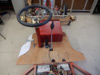
Seat bottom and back moved to the rear about two inches

DSCN5741.JPG

Redesign of the floorboard for additional foot resting area. (Template)
The soon-to-be-completed parking brake handle.

DSCN5743.JPG
 
Looks good...but your claymore labelling on that seat back is incomplete. ;)
 
You may be asking...why does he keep posting the same pics? Yes, they are very similar, but those who follow the minor changes will notice those changes.

Today's batch is a result of having to reinstall the body on the frame....solo I might add. A different rigging method and careful swing and sway and I managed to get it on.

After making the frame mods for the seat area, I needed to see how much room I gained. Not much, but a little more trimming and it will be good to go.

This pic gives us a great view of the front 'dashboard' and clearance for the carpet.
The carpet is the same as the final one except this one is a working tool and is dirty.
And what if any will be cosmetic issues where the body joins the frame (look near the tire)

DSCN5745.JPG

Another view of depth clearance for the fresh carpet that will cover all the wood floorboard.

DSCN5746.JPG

Easy access has been planned and seems to be OK.
However, I won't know about the dash panel once the switches, etc. are installed.
Wiring is only roughed in, so it is much tighter than the final result.

DSCN5747.JPG

And now for the exciting pic. Is this thing looking cool or what?

DSCN5749.JPG
 
Last edited:
About all I can say, timelinewise, for any of my projects is that they are certain to happen this century, or never. ;)
 
Took time off from updating.

With our mornings in the 17-20 degree range, I wait until late morning ...10-11ish to get started.
I work for about 2-4 hours on a good day.,.

I have started using some 1/8th oak panels I was gifted.

A top for the instrument panel, sans cutouts, and an insert for the back window.

DSCN5764.JPG

The rear 'window' will be fitted with a perforated metal panel, (shown) for rear visibility.
It will be painted with a complementary color, and some artwork as well.

I haven't decided whether to cover the wood with fabric, paint it, or leave the wood look, my favorite. I'm having trouble choosing a complementary color for the metal insert. The faintly visible bracing will be removed.

DSCN5768.JPG

I designed a 'nerf' bar for the rear.

FYI, for those who may not recognize the term,

The origin of the "hot rod nerf bar" can be traced back to the early hot rod scene, particularly popularized by the "California Kid" - a 1934 Ford three-window coupe owned by Pete Chapouris of Pete & Jake's Hot Rod Parts, which prominently featured a distinctive front nerf bar design, considered a classic "hot rod" aesthetic; this style was then widely replicated and adopted by other hot rod enthusiasts, making the nerf bar a recognizable feature on modified cars from that era.


DSCN5769.JPG

I designed the 'Nerf' bar using old/new finials, EMT pipe, swing springs, and a 1x1 square tube for the mount.
The brown 'sleeve' is used to hold the bar from sliding. It presses up against another tube wedged inside the spring.
The complete bar will be painted, warm gold, the same paint used on the rest of the car. The finial color...????.

DSCN5762.JPG

Making upholstery templates with foam board.

DSCN5766.JPG
 
Last edited:
Red does seem to be the obvious color. I'll be putting my touch on it though, to give it some contrast of its own.

It's raining here and I don't dance in the rain. But I do a mean 'jig' inside.

What you have before you is the beginning of two brackets to hold my recently acquired side lamps.

I'm using 1/8 x 1 flat stock.

DSCN5771.JPG
I finally decided on these path lights. They don't come with proper brackets.

All that remains is to drill the mounting holes into the car body and the lamp bracket. Then a coat of warm gold paint.
That should make them pop against the red. I will weld the attaching nuts on the inside of the body panel.

Oops, I almost forgot, I will weld on a 1/4" solid rod on the tips of both brackets.

DSCN5775.JPG

Are they going to be operable, you ask? Not at this time...no reason to.
I do have a surprise for inside the lamp though....that is for later ;)

DSCN5774.JPG
 
Lanterns modified

Sans paint, all that remains is to weld on the 1/4" rod to the bracket ends.
Oh yeah, and there is still the surprise for the inside of the lanterns...😈
DSCN5778.JPG

Does the top 'ball' look familiar?

And what do you suppose the bottom extended tube is from?
I'll reveal the answer in my next post. In the meantime, have a guess... :unsure:

The winner will get an all-expense trip to Nowheresville in the land of Not.DSCN5780.JPG
 
Lots of different REDS. Story time. Bought a used [Milwaukee Hydraulic Floor Jack - Model 40 - 4 Ton] Nice jack. Goes real low and real high. Sorry no pictures. If you have the internet? Go search. OK back to story. Took jack all apart. Had all the parts sandblasted. Took jack parts to powder coating guy. Picture a guy with powder stuck to his glasses. He said what color? I said surprise me. Went to pick it up. WOW the nicest glossy RED I have ever seen. I said "what color is that? He said "Soda Pop Red."

Try this? From Coca-Cola Red Color Codes History

#D00013
#F40000
#F40009

Enough mixing colors with the Text color thing. Its fun to play with colors in Photoshop. I can smell the paint. Respirator.

Forgot to say - Guy named Jack rebuilt the hydraulic part of my jack.
 
Like light brackets. Reminds me of wrought iron railings.
Whats going on with pictures I steal from the internet. .webp .avif?????? The world would be better if all pictures were JPG. Use -
DSCN5775.JPG

Hbd37c5e9b16745098b04e9c675d7cf03s.jpg_720x720q50.jpg
 
And Marty wins the trip to Nowheresville. I cut the bottom 3 1/2 inches off a couple of plastic funnels.
The black balls on the top are from bungee cords.

Progress report
I've been busy cleaning my shop and sorting the remaining bagged/tagged parts. (finding lost parts/tools is always fun).
Cleaned and prepped my homemade paint booth, anticipating its use soon.

Addressing the appearance of wavy side panels. They are made from 20 gauge sheet metal and are virtually flat, The wavy look is more than likely caused by the camera and lighting. Also, some grinding marks that have yet to be smoothed out.

I'm soon to order the body filler and paint for the next stage. Virtually all of the body is flat and only requires a skim coat of 'lightweight filler, if any. The welded edges require heavier-duty filler, with most applications being 1/8th or less.


Dupli-Color 11oz. Red Anodized Coating Automotive Spray Paint (MC200) (12 cans/132 oz)

I've found that 'decanting' spray cans is more cost-effective than other purchasing options. (.78 per oz)
Better yet, there is no thinning, mixing, reducer, etc. It's ready to spray using a proper spray painting gun and equipment.
 
Last edited:
Back
Top