CA Speed all whacked with Infineon XC846 72V Controller

Hi GCinDC,
During the weekend, I finally installed my "standard" 9C kit from eBikes.ca.
The kit comes with a CA (direct plugin) and in the CA manual, it is stated that the number of poles can not exceed 14.
BUT my CA was initially configured with 23 poles :shock: .
I was surprised of this discrepancy but after 60 km what I can say is the following: with the correct wheel dimensions, the speed seems accurate even at "high" speed (50 km/h) and more important the distance IS accurate (on a 400 meters known route).
I plan to install my normal odometer to check this.
Please, keep us informed if Justin contact you.
Martin G
 
the current is going out of the FETs through the shunt and then back to the battery. the shunt has a fixed resistance, i think the wire is called constantin which is a made up word like a trade seal that means the resistance remains constant, over temperature changes. so when the current flows through the shunt, there is a higher voltage on the FET side of the shunt than the battery side, top of the shunt and bottom of the shunt. by ohms law V=IR where R is the resistance in the shunt wire. you can lower that resistance by adding solder to fill in the space between them.

so the mV is measured on isense on top of the shunt and the ground for that is on the bottom.
 
MartinG said:
BUT my CA was initially configured with 23 poles...
..with the correct wheel dimensions, the speed seems accurate...

Interesting. Do you mean if you toggle through the setup, under poles you see 23? i didn't know that was possible!
What is the wheel size setting?
Did you get the CA & ebikekit together? Perhaps they were pre-configured...

dnmun said:
you can lower that resistance by adding solder to fill in the space between them. so the mV is measured on isense on top of the shunt and the ground for that is on the bottom.

hi dnum, so the shunt has a fixed resistance, but once it's coated with solder, that resistance changes (is lowered). is it possible this decrease could interfere with CA metrics? i suppose i could measure it as well from various points with the multimeter.

i'm starting to suspect that something completely unrelated is misconfigured. perhaps i should ship this off to an expert for diagnosis.

ps. there were a couple times last week when i turned on the controller switch, and instead of the splash screen, i saw a top line of WingDing type characters. That did not occur today... :roll:
 
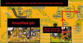
GC. The SP wire is the one labelled "Hall". Solder this to SA as shown top right in your photo.
 
Thanks for continuing to play the wheel of fortune, Mike!

Again, please pardon my ignorance. :oops:

My (orange) SP wire, the Hall is wired according in the hall (blue wire) spot according to knuckles photo.

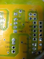
Are you saying I should move it to the spot on the board marked SA, as per this (background) pic:
SA.jpg

thanks,

greg
 
GCinDC said:
Interesting. Do you mean if you toggle through the setup, under poles you see 23? i didn't know that was possible!
I meaned exactly that ! When I checked the setup, it was already set to this value (23). The CA firmware (on the splash screen) is version 2.11.
GCinDC said:
What is the wheel size setting?
I set it myself after measuring the actual wheel: 2,150 mm for a 700Cx35 tire (on a Mavic A319 rim laced 1 cross by myself).
GCinDC said:
Did you get the CA & ebikekit together? Perhaps they were pre-configured...
Yes, it was a complete package. The # of poles was certainly pre-configured but the wheelsize was a default incorrect for my real wheelsize: so I changed it.

My odometer is not installed, but I just got back from some errands and I computed the distance on google maps. The computed distance is 3,662 km and the CA value is 3,654 km: I consider the results the same. The distance being correct, I assume that my CA is working correctly for the speed and all statistics involving distance and speed.

The complete setup is as follows: 9C front hub motor (model 2807), 20A Infineon controller, 36V 8Ah NiCad, Direct Plug-in Cycle Analyst (V2.11 Firmware), plus throttle, charger, etc.

The only thing different from your setup, seems to be the controller and-or the voltages and amperages involved (my novice 2c worth...)

Martin G
 
GC, that's correct. Move that wire to the SA pad. As has been discussed elsewhere the Infineon controllers do provide a speed output pulse but it is not very useable, that's why we just tap into one of the hall signals. You'll need to change the number of hall transitions in the CA setup to match your motor.
 
I have seen this before.

First off - yes, you must run both the GND and the SHUNT(-) wires separately and you should terminate them at the same spot
This is called a 3 wire measurement
It is critical that you have two paths.... DO NOT tie them together and run one wire.
I will spare you the technical explanation.

as far as your noise -

If your hall is in fact tied to one of the three hall sensors directly (A, B, or C) and you are still seeing this glitch above a certain speed this is due to a low signal to noise ratio.
Shorten your hall wire as short as you can and the problem will go away. Even another foot or two of wire will cause issue.

I had the exact same problem on a test bike that was using a hall extension wire as an adapter.

While you have the controller open check all the hall solder joints... Those extension cables you have are making my a little nervous :?

-methods
 
Mike1 said:
Move that wire to the SA pad.

That goes along perfectly with a PM I just got:
geoff57 said:
...Looks like you have the right connections for pins 1 through 4 pin 5 is the hall sensorwire and should be soldered to one of the hall sensor inputs SA,SB or SC. pin 6 is the E-brake wire on the originaly on analog xtyte controllers this could be fitted directly to the brake line on digital controllers you have to be more creative, the soloution has been around for a long time now, the neatest version I came up with in the 18 fet thread see this link http://endless-sphere.com/forums/viewtopic.php?f=2&t=10312&p=187274#p187274.
keep an eye on of the all infineon family of controllers threads you will be able to use a lot of what you find even if it was not for your controller.

You WILL need to calibrate the Rshunt setting in the controller from the looks of things you have all the bits to follow methods way in this thread http://endless-sphere.com/forums/viewtopic.php?f=2&t=12316 on how to calibrate the CA Rshunt setting.

Geoff


Okay, so last night I moved the wire to the SA pad. I did NOT move the eBrake wire. I tested by lifting the wheel and accelerating. It seemed to spin fine. The CA speedmeter reading increased with the throttle but seemed to top out at 39mph, before top speed, but definitely an improvement. Perhaps it would need some wheel size adjustments, but at least I'd be able to ride it to work today...

This morning, I adjusted the wheel size and headed off, but after 10 feet it cut, then started, then cut, then started, then cut. Downhill it went for 50 yards before cutting. Uphill it cut much sooner. No loss of power to the CA, just power to the motor... I needed to get to work, so I took it all apart and moved the SA wire back to SM. :roll:

Mike1 said:
You'll need to change the number of hall transitions in the CA setup to match your motor.

Hmm, is this the Poles setting? If so, per Justin, because the GM motors have 23 poles, I'm to set the poles to 14, and then wheel size to 14/23rd the real size. That setting worked fine for previous controller.

methods said:
First off - yes, you must run both the GND and the SHUNT(-) wires separately and you should terminate them at the same spot.

same exact spot?! Both GND are on the same spot, bottom of shunt, bottom of board. The ISense (SHUNT -?) wire, however, is soldered underneath the far peak of the M... Should I solder them all at the exact spot?

methods said:
If your hall is in fact tied to one of the three hall sensors directly (A, B, or C) and you are still seeing this glitch above a certain speed this is due to a low signal to noise ratio.
Shorten your hall wire as short as you can and the problem will go away. Even another foot or two of wire will cause issue.

I had the exact same problem on a test bike that was using a hall extension wire as an adapter.

While you have the controller open check all the hall solder joints... Those extension cables you have are making my a little nervous :?

-methods

The CA Hall wire is soldered to SM. Is that an A B or C hall sensor?

I'll shorten the hall wires as much as possible.

In the meantime, what is the proper method to splice wires? I cut, strip off the ends, twist and solder them. Then cover with shrink tubing and tape. If we're talking mV, is there a chance this splicing method will skew the numbers?

PS. What about the extension cables is making you nervous? The bottom of the board sure is a lot easier to access with a soldering iron... is it the extensions floating down there next to the pointy tips..? :shock: should I insulate the wires more?
 
The SM pad is not A, B, or C
Someone above pointed out with a picture exactly where you need to tap in.

The reason your bike is cutting out now is probably because the CA is hitting the brakes when you cross either the speed limit or the current limit.
Unplug the CA and you will probably resolve the issue.
Alternatively reset the current and speed limits in the CA

The GND and Shunt(-) wires dont have to be perfect or in the exact same spot.
Just make sure that they are not at opposite ends of the board. I saw your pictures - they look fine.
You just want them close together - no need to get more exacting than that.

It sounds like you have not moved your speed wire to SA, SB, or SC.
You need to do that as prescribed above. Dont bother shortening your hall wires until after you do this.
I had assumed that you already tapped A, B, or C

-methods
 
methods said:
The reason your bike is cutting out now is probably because the CA is hitting the brakes when you cross either the speed limit or the current limit.
Unplug the CA and you will probably resolve the issue.
Alternatively reset the current and speed limits in the CA

Wish I tried this. I will double check but I'm pretty sure Speed limit is set to 99mph and Max Amps is set to 200 Amps. lol.

methods said:
It sounds like you have not moved your speed wire to SA, SB, or SC...

Ah, ABC, as in SA, SB, SC... :lol:

I DID move the hall sensor wire (is what everyone's calling the SP wire?) from SM to SA, but got the cut outs, so then moved it back in order to ride it...

Rshunt, fyi, is set to 3.122 mOhms, per nicobie's note on the bottom of the controller. Could that setting have changed since moving the GND's?

Tonight I'll:
- move the SP wire back again, from SM to SA
- test w/ CA off
- do a full reset of the CA. (got new batts, so was gonna do it anyway)
- reconfigure CA
- pray and test again

In the meantime, Methods, how much for a 85V 40A controller, preferably shorter than the 18 fet..? I read that you've got a new product hitting the market, but not sure I need all that. :D

Thanks,

Greg
 
GC, I would recommend disconnecting the brake wire until you get everything else sorted out. That should prevent the CA from shutting your controller down.
 
Thanks, Mike. I'll do that.

Meanwhile, I reread Geoff's post, and the link off of it:

geoff57 said:
pin 6 is the E-brake wire on the originaly on analog xtyte controllers this could be fitted directly to the brake line on digital controllers you have to be more creative, the soloution has been around for a long time now, the neatest version I came up with in the 18 fet thread see this link http://endless-sphere.com/forums/viewtopic.php?f=2&t=10312&p=187274#p187274.

the post linked to:
geoff57 said:
methods said:
How to wire in the CA speed control:

The lazy way to do it is to just tap the ebrake.
This will allow you to use the LVC feature in the CA

To use the speed control and current limiter you need to tap the throttle line.
As we all know, a diode goes inline between the CA and the controller input
We also put a 2K - 5K inline between the controller and the throttle

If you do this with an 18 fet you will be disappointed :mrgreen:
Your throttle signal will be limited to around 2.8V


This is because the 18 fet runs a 10K to ground and a 1.8K inline with the throttle signal.
This means that you dont need the external 2K - 5K resistor
Solder the throttle line in as normal.
Follow the trace from the SP terminal right into the 1.8K resistor.
Anywhere after that, scrape a trace and solder in a tiny tap wire. Dont just solder the leg of the diode onto a trace - this is too risky. It is better to solder in a tiny flexible wire to eliminate risk of fatigue. The traces are tiny and you dont want to be yanking on them.

There are ample points to tap...

Anyhow - thats how you do it.

-methods
hi
I have an alternative to that.
If you are not using a sensorless adaptor board then you should have the SLA pad free this is a spure off the track going to the chip after the resistor, the SLA track has its own resistor on it this is 3.3K ohm you must short the resistor with a bit of wire and some solder, all you have to do is place a diode in the SLA pad the right way round with the other end attached to the CA and you have done the job no scraping of tracks needed if wanted put a switch in to disable when not wanted as well that is up to you.

Geoff


Still mostly Greek to me, but it seems to have something to do with the throttle...

FWIW, I have a magura throttle with a manually adjusted POT and a 1K resitor inline with the + and another 1K resistor inline with GND on the throttle line. This results in the desired range, something like 1.2 - 3.8V...

Could this be a factor?

Anyway, will test tonight w/o Brake wire.
 
Mike is right. Here is why:

Even if the speed limit is set to 200mph the CA could "think" it is hitting 200mph if you have a noisy hall input or you have an inappropriate #poles setting.
By disconnecting the ebrake line you change the CA to an "indication only" component instead of a component in the control loop.

new subject:

You said something that did not make sense to me: You said that you changed the Speed line from SM to SA and got cutouts so you moved it back.
If anything, the SA (or SB, or SC) should work better... I believe that the SM pin will pulse something like 6 times for every one time an SA will pulse.
(can anyone confirm that?)

Do this:
* Remove the Ebrake line
* Attach the CA speed input to SA (hall A) pad
* Set the # of poles in the CA to the correct number for your motor

Carefully inspect the hall sensor pads (+5V, GND, SA, SB, SC) both on the top and on the bottom. Make sure that there are no poor solder joints or tiny wires causing shorts.
Measure the length of your Hall cable. If it is longer than 48" trim it down if possible.

This should get you back to a point where you can run the bike up to speed (in a test stand freewheeling) and read that speed on the CA.
There are two possible troubleshooting paths now:

1) The speed does not read correctly
2) The speed does read correctly.

If it does not read correctly then it is either a problem with the hall wiring or a problem with the CA programming. Dont ride the bike till this is sorted out.

If it does read correctly then go ride the bike. If the bike now cuts out you know it is due to something else in the system. Since the Ebrake line is disconnected you know it is not the CA so that leaves several things including:

* Noise on the hall wires
* Poor phase connections
* Poor battery connections
* BMS from battery kicking in
* Bouncing off of controller LVC
* Other intermittent load dependent connections

There are also a few other things that could be going on such as your 12V or 5V buss being loaded down but I dont think it is that complicated.
You should be able to test all of this on the bench in one shot.
Set the bike upside down and put the CA and controller on your work bench.

-methods
 
You got a post in before mine went up.

Please eliminate all variables.
Do you have a standard throttle to use? If so, use that.

You have too many variables right now so try to make as many things "known good" as possible.
Follow one troubleshooting path and change only 1 thing at a time.

-methods
 
Thanks, Methods! I'm awed and grateful for the time all of you have spent helping me on this!!!

Alas, no news today on this.

Last night, I had to reconfigure my wife's BionX ebike (while we return the weak 250 PL battery.) I stuck a 9C on the front, rigged up my old GM kit controller and Ping 48V 12Ah. First experience w/ front wheel - It burns out! LOL. A little dicey on the loose stuff though - she's 7 months pregnant! :shock: She'll go easy though.... And it'll be a big help for her, pulling the two kids in the trailer up some steep hills! We are totally dependent on our ebikes for commuting, carting the kids etc, so a backup was necessary. (PS. To answer your Q, that's WHY I moved the SP wire BACK to SM; to RIDE it into work; I couldn't ride it stuttering and ran out of time diagnosing. Obviously I shoulda unplugged the CA)

Anyway, after my wife's ebike, I weighed my options. I could troubleshoot the CA speedometer, or.... :twisted:

I could pull the two new Turnigy 5s 5Ah packs out of their boxes and admire the new wet noodle wiring... You guessed. It was 1AM when I finally finished soldering up a new 5s8p charging & 20s2p discharging harness, with db25 connectors for the balance leads, one that goes to 4 lipo buzzers, and the other that parallels them to charge, so now I only have two connections to make when switching... pics eventually. once i mount the female db25, then it should be presentable...

I'll get back to the controller tonight... and it's probably time to replace another set of brake pads :roll:
 
Okay, news. Per the instructions, I:

- Removed the Ebrake line (actually cut it outside the controller after i noticed what seemed like cut outs during lifted wheel test)
- Attached the CA speed input to SA (hall A) pad (see pics below)
- Set the # of poles in the CA to the correct number for your motor
Well, the CA maxes at 14 poles, GM motor has 23, so per Justin, we compensate by lowering wheel size 14/23rd of ... 26 X 1.9 Diameter -> (80.63 inches or 2055 mm) = 1250 mm. But because there are many more phases than cycles (per Philf), (and I hit 99mph on the CA at 15 mph), I arbitrarily set the CA wheel size to 330 mm, and surprise, the speed compares favorably with my bike computer's speed reading!........ well sometimes. other times, it acts like it's on acid. :roll:

For example, if I go 20mph, the reading will spasmodically jump between 200mph, then 20 mph, then 2 mph, then 200 again... but sometimes it's right so i must be getting somewhere... :lol:

perhaps it is noise in the hall wires.

(confession: i tested this ONLY with the magura throttle... :mrgreen: i'll change out tonight to test again.

and now for the pictures from this morning's surgery:
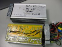
IMG_3418.JPG
I taped up the loose GND wires to add insulation.
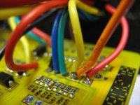
IMG_3434.JPG
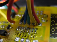
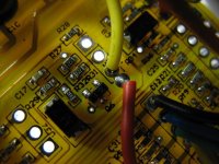
Halls before moving wire to SA(what did you guys do before Macro photos?)
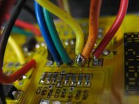
IMG_3422.JPG
Halls after moving wire to SA. (Cut both wires clean, stripped & twisted them, poked them through hole, with soldering iron tip on the bottom of the board.
IMG_3432.JPG
Then added a bead of solder on top for good measure.
IMG_3433.JPG
Halls from the bottom
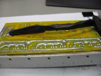
IMG_3419.JPG
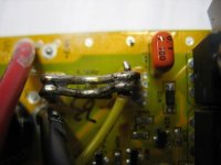
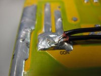
Ye Old Shunt
IMG_3428.JPG
Two GND wires soldered to bottom of board, bottom of shunt
IMG_3420.JPG
eBrake lines, red line cut eventually outside the controller.
IMG_3423.JPG

Next steps:

- Test w regular hall effect throttle?
- Eliminate noise on halls?

ps. I did not yet do a full reset of the CA
pps. Last night after my commute home, I toggled through the CA screens and the time read 4m45s, or something like that. My 5 mile commute takes ~15 minutes... so where is it getting that time from? I'll recheck this again tonight. I'm not as familiar w/ the lower level screens...
 
Ok - ignore the CA reading - that is easy to fix.

Are you or are you not getting cutouts?
Go ride the bike. :mrgreen:

If you are getting cutouts then you have a serious problem that we need to address.
If you are not then all we have to do now is tune your CA - which may or may not involve lowering the noise on your hall lines

I have been thinking about running 15V on the hall line instead of 5V.....

-methods
 
No cutouts w/ CA ebrake line cut!

Bike rides like a dream! (83V of lipo hot...) :twisted:

methods said:
If you are not then all we have to do now is tune your CA - which may or may not involve lowering the noise on your hall lines

I have been thinking about running 15V on the hall line instead of 5V.....

-methods

The phase/hall wires can't be much more than 3.5' ft. I'll check. They come out of tire, run over to bottom braket, half way up seat tube and then under my controller to the front... The connectors are crappy, and I did splice them at one point. would like to replace w/ clean molex(?) or something if i could find them...

Re 15V on the hall line.... I'm game! 8)

Thanks!
 
Ok - so the official cause of the original problem was that the CA was registering peak speeds which were above 99mph which caused it to pump your brakes.

Now - to address the CA

There are several things that could be causing the CA to read poorly and there are several solutions:

1) Avoid the problem

You could install a magnetic speed sensor on your wheel. They cost about $1 - you put a magnet on your spoke and ziptie a magnetic switch on your fork.
You open up the back of the CA, cut the yellow wire, solder in 1 new wire to ground and 1 new wire to the SP pad - drill a hole and you are in business.
This is the easy way out

2) Identify the problem

This can be tricky. Here are a few common things that can cause a poor signal on your hall sensors

First off, the controller is happy so this tells us that the motor must be getting +5V, GND, and SA, SB, SC
So there must be at least a reasonably good connection between the controller and the motor.
You re-did the CA ground and Shunt(-) so we assume that the CA is on the same ground as your controller.
The CA appears to be performing normally so we assume that it is getting good +V
This leaves the speed wire between the CA and the Controller.

* Poor solder joint at pin SA on the controller
* Poor connection at the JST 6 pin "CA Connector"
* Poor solder joint inside the CA.

Ideas:

Remove the 4 screws in the back of your CA. Measure the resistance between the pin that has the YELLOW wire soldered to it and the very end of your controller hall wire down by the motor.
This will effectively confirm that you have continuity between the CA ground and the ground that the actual hall sensors see.
Should be much less than 1ohm
Remember that the CA is conformal coated so you will need to "dig" down to the pad.


Going back to the software -> I suspect your speed calculations.
If you know the actual number of poles your motor has (this does not necessarily mean stator poles or magnets) then you should be able to use Justins hack of 14/23 or 14/X
If this formula does not work out then you dont have the correct number of poles.

AH! I just had an Idea.

What voltage battery are you using?

If you are reading the speed just fine at low speeds then at higher speeds it craps out it could be that your +5V rail is getting soggy.
Please tell me:

-> What battery voltage you are running
-> What value power resistors you have in your 14V regulator


So... eh... how does my original idea of just hooking up a speed sensor sound now :D

-methods
 
I misspoke above:
If you decide to open the CA-

measure from:
Yellow wire at CA board to Yellow wire at motor hall connector

Measure from:
Ground in CA to Ground at end of motor hall connector

Both should be <1ohm

-methods
 
methods said:
* Poor solder joint at pin SA on the controller
* Poor connection at the JST 6 pin "CA Connector"
* Poor solder joint inside the CA.

-> What battery voltage you are running
-> What value power resistors you have in your 14V regulator

i'll check the connections you suggest, and peek into the CA.

i'm running 20s2p lipo, so 74 nominal, 83 hot.
how do i identify the power resistors? and where's the regulator?... :mrgreen:

more observations, fyi, until i can get in there:
- sometimes when i turn the controller on, the CA splash screen is gibberish. it returns to normal after the splash.
- since moving the SP wire to SA, the speedometer no longer is accurate up to a certain speed. that was true before moving the SP wire. now, it jumps all over all all speeds sometimes reading 300mph when i'm going under 10mph.
- the CA works fine with another controller! that controller is a 75V 30A (from steveo). i thought that one got fried, but, as fechter diagnosed, the 5+ line to the controller switch came off.

if the CA works with another controller, should i still dig into the CA?

i'll try the hall effect throttle and then recheck the connections.

thanks!!!
 
.
.
:?

(big sigh)

No - dont dig into the CA.

-methods
 
"- sometimes when i turn the controller on, the CA splash screen is gibberish. it returns to normal after the splash."

This is telling me that you have a power issue with your CA. You should never see garbage on the screen, this means that something is going wrong at startup and it is probably because there is not enough juice on hand.

I now suspect your CA ground - this would explain both issues you are having.

Perhaps one of the wires is internally broken and only a few strands are still connected supplying just enough current to keep the CA running but not enough to handle the inrush currents?

Dooes the CA read the correct voltage?
Does the CA read the correct current within reason?
Does the backlight change brightness when you twist the throttle?
Does the backlight change brightness ever?

That pigtail you are using is not a standard CA pigtail. Looks similar to the pigtails I have but different colors yet. I checked all your color coding and it is correct. Please inspect the pins and sockets to make sure that a pin/socket is not "pushed back".

Has the CA ever turned on with "crap" on the screen with your other controller?

You are close to finding your problem.
If you were here we would have it sorted in 5 minutes :mrgreen:

-methods
 
Dooes the CA read the correct voltage? YES
Does the CA read the correct current within reason? YES
Does the backlight change brightness when you twist the throttle? NO
Does the backlight change brightness ever? NO
Please inspect the pins and sockets to make sure that a pin/socket is not "pushed back". CHECKED, The're pushed in, look good.
Has the CA ever turned on with "crap" on the screen with your other controller? NO

I took a vid of the CA (sorry i missed the splash). At first, i open the throttle as little as possible and hold it steady for a while, then open it up, then let off.

[youtube]Z2yuruef9GA[/youtube]
 
Back
Top