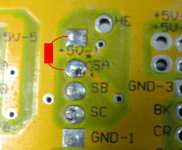
CA Speed all whacked with Infineon XC846 72V Controller

My first experiment would be to try a pull-up resistor at the CA end of the speed line (maybe around 1K for starters). If things improve, you're seeing noise. If the problem persists, the signal you're getting from the source is genuinely bogus.

The old-school way of passively terminating a TTL signal is to take that signal to +5V with a 220 ohm resistor, and also to GND with a 330ohm resistor. Obviously, this directly presents the power bus with a 570 ohm "load" in the process, and that'll pull just short of 9mA by itself. But it worked well!

Long weekend coming up... Maybe I'll get a chance to jump back into the fray, here. It's no secret that reliable speed/distance measurement is a pet peeve of mine :).
 
philf said:
My first experiment would be to try a pull-up resistor...

Thanks Philf, this will take some time (and a glossary) digest. (lost me with terminating a TTL..)

I'll be happy to try that, but meanwhile there's a new clue:

I'd said the CA worked fine w/ old controller. That was only partially true...

- This morning I tried to hook up the hall effect throttle, but couldn't match connectors...
- On ride in to work, I noticed the speedometer on the CA seemed to be working! :shock: Was it the connection? There was NO FLICKERING of the speed reading as I coasted down the street at 6mph, 7mph... CA speed matched bike 'computer' speed (front wheel magnet type).

So then I hit the throttle... Instantly the CA speed read 600+mph! I read gibberish, until the speed stabilized, and then it bounced around like normal... :roll:

So the clue is that CA reads the speed fine when rear wheel is freewheeling, but not under throttle...

Now the backstory. Let's go back in time...

The infineon arrived on the same night that i fixed the old controller (thought it had fried but was just a broken switch line). After I fixed the switch line, I turned it on, saw that it worked, and then decommissioned it because I was told it can't handle more than 75V. So then I cannibalized its connectors to put on the Infineon. I can't test it until I replace the connectors.

Out of the gate, the Infineon:
- Speed was whacked
- Throttle had short range.

The speed we've been focusing on, but let me tell you about the throttle...

When I first got the Magura (June?), I read in a thread that the thing to do was to open it and adjust the gear (POT) and then to wire inline resistors. Well, I adjusted the POT and found that I didn't need resistors; the throttle had good range, so I punted on the inline resistors.

On the infineon however, the range was too short. No idea why it was any different. But then I found this post:

methods said:
I just tuned in my Magura Throttle...

The general idea is that the Infineon only has a throttle window where it will work:

Dead zone 0V - 1.3V
Active zone 1.3V - 3.2V
100% throttle zone 3.2V - 3.8V
Upper Dead Zone 3.8V - 5V

This is tuned to the typical hall sensor throttle.

The throttle MUST be below 1.3V for the controller to initialize
The throttle MUST stay below 3.8V else you will get throttle cut-out at WOT

So... The idea is to use series resistances before and after the throttle to tune in the maximum resolution
There is no point in having a region of your throttle that moves with no reaction out at the wheel....

Anyhow, ends up that if you put a 1K resistor in line with the +5V and a 3K resistor inline with GND it is near perfect.
You will see:

~1.15V at the lowest setting
~3.65V at the highest setting

So I trotted off to the Shack, bought the assortment of resistors, tried the ones suggested, but perhaps because my pot was already manually adjusted, i found that the range was perfect with a 1k ohm resistor inline with the +5V and another 1k ohm inline with GND.

Throttle problem solved.

But have I created another problem?

Incidentally, I just noticed another thread below methods by nicobie, who sold me this exact controller! (He sold it not because of the throttle, but because he couldn't get it to work on his BMC....)
nicobie said:
methods said:
I just tuned in my Magura Throttle -methods

Hey -methods,

I tried something like that on my hall throttle controlled Infineon (12 fet) w/ BMC 600w hub and didn't have any luck.

I bought a couple of 1k mini pots and wired them in series on the 5v and grd wires. When the pots were set to anything over 125 ohms the motor wouldn't run. I tried them at 75 and 100 ohms each and didn't see a difference from stock. I used the same settings on both pots for each test.

Do you think a Magura throttle tuned with resistance like you did would help? It's not too bad at 52v, but when I switch to 75v the bike is almost unrideable.

Nick
 
Try Philf's suggestion.

Did you say that you disassembled the Magura throttle to adjust the internal pot?
I am interested, have a link?

-methods
 
I think this is the original post I followed on the Magura is: Re: Throttle types, brands, quality, ruggedness, etc.

okay philf, can you tell me if i've got this right:

philf said:
My first experiment would be to try a pull-up resistor at the CA end of the speed line (maybe around 1K for starters).

What's a "pull-up" resistor? Can I use an inline one?
Should I snip the speed line (orange) and put the 1K resistor inline? (not soldering it, just twisting it together or taping it temporarily?


philf said:
If things improve, you're seeing noise. If the problem persists, the signal you're getting from the source is genuinely bogus.

If things improve = If the speedometer reading doesn't jump around?
If the problem persists, the signal you're getting from the source... the source = somewhere along SP wire, up to the SA hole?

Thanks!
 
Greg, you don't have to snip anything.
A pull-up resistor is simply a resistor connected between the hall input and 5V. What it does is keep the hall signal to the CA at 5V unless the hall sensor in the motor is pulling it down. This should then give a nice clean signal for the CA to read.

Phil, I assume you are suggesting that he uses the pull-up on the 5V line and not VCC :?:
 
Mike1 said:
A pull-up resistor is simply a resistor...

good, so i've already an assortment of resistors... :wink:

and since i'm a moron...
philf said:
...try a pull-up resistor at the CA end of the speed line
Mike1 said:
...connected between the hall input and 5V.

here?:
pullupresistor.jpg

or on the other side of the board? do i have to pull of the SP line from SA?

thanks, remote doctors
 
there should already be a pullup resistor on the hall sensor leads. go look over where the hall sensor leads come on to the pcb and see if there is a set of resistors all identical connecting each of the hall sensor lines up to the 5V power of the hall sensors.

someimes they use a resistor array soldered on top, sometimes they are discrete surface maount resistors, but you will see three side by side, on the hall sensor traces between the microprocessor and the place where the leads are soldered onto the pcb.
 
The idea is to put the pull up resistor at the CA end.
Pop the CA off the bike
Remove the 4 screws
Pull off the back cover
Locate the local +5V buss
Solder a 1K resistor between the +5V buss and the Speed wire

He surely does *not* mean to tie into V+. That would release magic smoke.

Anyhow - you want to make this mod right at the CA to eliminate variables.

-methods
 
make sure you use a big enuff resistor to keep the total current that the hall sensor has to sink under 8mA. do you know the voltage on the 5V rail? if you are sinking current from the controller and the CA together then it could overload the hall sensor.

you gonna be a hacker yet.
 
Good point - both the controller +5V and the CA +5V rails have limited current capacity.

I have not tested the CA +5V rail but it is marked "+5V" on the V2.11 so I assume that it is right at or around 5V.

After this I think he should try running 15V on the halls :mrgreen:
I want to try it myself but I am too lazy to open up my controller :p

-methods
 
looked inside CA. sure don't want to ruin it...

so, are we debating this course, now, vis a vis the rails?

is the plan still to solder a 1K resistor to the +5V spot and the SP spot, w/o moving the existing wires... right?

i could redo some my hall effect throttle connectors to test that, or are we thinking the throttle isn't the issue?
 
i actually haven't followed too closely. but i saw the comments about the extra pullup resistor on the hall sensor output and worried that you would exceed the current rating on the hall sensor.

they can sink about 8mA i think, but it could be 6mA. more than that is bad. if your controller has 223 on the pullup resistor then that is a 22k ohm resistor, if it is 222, that is 2.2k ohm.

if your controller 5 volt rail is really 5V, which is yet to be determined since we don't know how well the regulator works, then the current that the hall sensor has to sink is either .227mA or 2.27mA and so you don't want the pullup resistor on the CA to allow more current to flow out of the 5V on the CA than about 7mA for the 223 or 5mA for the 222 label on the controller pullup resistor.

does that make sense?

for 5mA then a 1k ohm resistor is ok from the CA 5V rail or if it is 2.27mA through the 222 resistor to the 5V rail on the controller, then you need to use a 2.2k resistor on the CA side. so when they are both sourcing current into the hall sensor, it doesn't burn out the hall sensor.

if they are both 2.2k ohm they will be in parallel and the equivalent resistance is 1.1k ohm and the total current the hall sensor has to sink is about 4.5mA. in spec. 5V/1.1kohm=4.5mA.

the reason the old shenzen controllers would not run the BMC motors at high speed is because the motor was turning so fast that the hall sensors were triggering faster than the individual pulses of the pwm controller so it just would go into a signalling seizure. this was solved by using a higher frequency crystal oscillator to drive the microprocessor at higher speeds so it could keep up. then the infineon was introduced and the shenzen controller was no longer sold by keywin, just the infineon. that thread is in the technical archives, really a great read on how richard figured it out.

so figure out what the pullup resistor reads, if it is 223 then use a 22k ohm pullup resistor on the CA or 2.2k ohm if it is 222.
 
Another approach would be to double the pull-up resistor value at the controller and add the same at the CA end. This would mean changing a resistor on the board though and Greg may not be too eager to do this. The other downside to this is that it may cause problems if you try to run without the CA connected.
 
After reading about this blue wire on the infineon controller that doesn't work with my stock analog speedometer even though my speedometer did work with the old stock controller. I have to now ask if it will work with the CA-SP version? If so can I just connect it to the CA speed sensor or do I have to actually mount the separate speed sensor and use the magnet provided with the CA-SP? If I have to do that then I wouldn't need the blue wire at all correct?

I guess what I am asking is this blue wire providing the same thing information to the CA as the magnet would when it passes in front of the sensor mounted on the fork? I read something that made me belive that might be the case, if so couldn't you use any sensor from a cheap bike speedometer to record the speed without going through the trouble of mounting the sensor and the magnet?
 
nogas4me said:
After reading about this blue wire on the infineon controller that doesn't work with my stock analog speedometer even though my speedometer did work with the old stock controller. I have to now ask if it will work with the CA-SP version? If so can I just connect it to the CA speed sensor or do I have to actually mount the separate speed sensor and use the magnet provided with the CA-SP? If I have to do that then I wouldn't need the blue wire at all correct?

I guess what I am asking is this blue wire providing the same thing information to the CA as the magnet would when it passes in front of the sensor mounted on the fork? I read something that made me belive that might be the case, if so couldn't you use any sensor from a cheap bike speedometer to record the speed without going through the trouble of mounting the sensor and the magnet?

So, do you have a CA? What's your analog speedometer? bike computer?

From my limited understanding, the speed wire sends a pulse, and then it's up to the CA or speedometer to calculate what those pulses mean. In the case of a wheel magnet, the pulse would be one revolution, but for a hall wire, which the blue wire should be connected to, but doesn't seem to be, there are more pulses than revolutions, because there are more poles or magnets. On the CA, you can set the number of poles your motor has and wheel size (circumference) so that the 'speed' can be calculated. That's my understanding.

What you should do will probably depend on what other equipment you have. Did you say you had a scooter?
 
GCinDC said:
nogas4me said:
So, do you have a CA? What's your analog speedometer? bike computer?

From my limited understanding, the speed wire sends a pulse, and then it's up to the CA or speedometer to calculate what those pulses mean. In the case of a wheel magnet, the pulse would be one revolution, but for a hall wire, which the blue wire should be connected to, but doesn't seem to be, there are more pulses than revolutions, because there are more poles or magnets. On the CA, you can set the number of poles your motor has and wheel size (circumference) so that the 'speed' can be calculated. That's my understanding.

What you should do will probably depend on what other equipment you have. Did you say you had a scooter?

Yes, I have a scooter XB-600 it has a analog speedomter in the dash that I hooked to the blue wire. It doesn't work. I also have a bike speedometer hooked up to a wheel magnet that I use now.

It sounds like the blue wire is a bust unless you have a CA computer Correct?
 
this issue is resolved. it was a connection. With the recent demise of my GM motor, I installed a rear 9C, having removed the hall pins several times to allow for nuts/washers/torque arms etc.

imagine my surprise that the CA speedometer no longer flakes. reads a steady MPH, just one or two mph above my bike computer (magnet to front wheel).

i feel like an idiot. it must have been a bad connection all along - wait a minute - with the CA connection? - as the motor wouldn't have worked with the halls acting up. hmm...

i'll recheck the CA connection, but it's fixed for now!

thanks to all who've helped, and apologies for the goose chase!
 
Back
Top