philf said:
My first experiment would be to try a pull-up resistor...
Thanks Philf, this will take some time (and a glossary) digest. (lost me with terminating a TTL..)
I'll be happy to try that, but meanwhile there's a new clue:
I'd said the CA worked fine w/ old controller. That was only partially true...
- This morning I tried to hook up the hall effect throttle, but couldn't match connectors...
- On ride in to work, I noticed the speedometer on the CA seemed to be working!

Was it the connection? There was NO FLICKERING of the speed reading as I
coasted down the street at 6mph, 7mph... CA speed matched bike 'computer' speed (front wheel magnet type).
So then I hit the throttle... Instantly the CA speed read 600+mph! I read gibberish, until the speed stabilized, and then it bounced around like normal...

So the clue is that CA reads the speed fine when rear wheel is freewheeling, but not under throttle...
Now the backstory. Let's go back in time...
The infineon arrived on the same night that i fixed the old controller (thought it had fried but was just a broken switch line). After I fixed the switch line, I turned it on, saw that it worked, and then decommissioned it because I was told it can't handle more than 75V. So then I cannibalized its connectors to put on the Infineon. I can't test it until I replace the connectors.
Out of the gate, the Infineon:
- Speed was whacked
- Throttle had short range.
The speed we've been focusing on, but let me tell you about the throttle...
When I first got the Magura (June?), I read in a thread that the thing to do was to open it and adjust the gear (POT) and then to wire inline resistors. Well, I adjusted the POT and found that I didn't need resistors; the throttle had good range, so I punted on the inline resistors.
On the infineon however, the range was too short. No idea why it was any different. But then I found this post:
methods said:
I just tuned in my Magura Throttle...
The general idea is that the Infineon only has a throttle window where it will work:
Dead zone 0V - 1.3V
Active zone 1.3V - 3.2V
100% throttle zone 3.2V - 3.8V
Upper Dead Zone 3.8V - 5V
This is tuned to the typical hall sensor throttle.
The throttle MUST be below 1.3V for the controller to initialize
The throttle MUST stay below 3.8V else you will get throttle cut-out at WOT
So... The idea is to use series resistances before and after the throttle to tune in the maximum resolution
There is no point in having a region of your throttle that moves with no reaction out at the wheel....
Anyhow, ends up that if you put a 1K resistor in line with the +5V and a 3K resistor inline with GND it is near perfect.
You will see:
~1.15V at the lowest setting
~3.65V at the highest setting
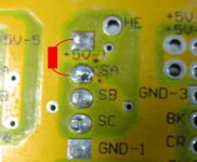
So I trotted off to the Shack, bought the assortment of resistors, tried the ones suggested, but perhaps because my pot was already manually adjusted, i found that the range was perfect with a 1k ohm resistor inline with the +5V and another 1k ohm inline with GND.
Throttle problem solved.
But have I created another problem?
Incidentally, I just noticed another thread below methods by nicobie, who sold me this exact controller! (He sold it not because of the throttle, but because he couldn't get it to work on his BMC....)
nicobie said:
methods said:
I just tuned in my Magura Throttle -methods
Hey -methods,
I tried something like that on my hall throttle controlled Infineon (12 fet) w/ BMC 600w hub and didn't have any luck.
I bought a couple of 1k mini pots and wired them in series on the 5v and grd wires. When the pots were set to anything over 125 ohms the motor wouldn't run. I tried them at 75 and 100 ohms each and didn't see a difference from stock. I used the same settings on both pots for each test.
Do you think a Magura throttle tuned with resistance like you did would help? It's not too bad at 52v, but when I switch to 75v the bike is almost unrideable.
Nick
 .
.

