Can you laser cut cycloidal gear reduction parts?

bobc

10 kW
Joined
Jan 20, 2011
Messages
993
Location
Knutsford England
I'm going to try it, just for fun: frankly I'm always stunned by the quality of the output from my local laser cutters.

I'll laser the 2 wobbly rotors and the rings and the output spider. Should cost me about £20
I might be able to laser the high speed end plate too, but I'll have to mill the high torque side...

I expect it'll work but be "a bit rough". Will it last? Will it "run in" & get smoother? I spent £29 on a 1kW inrunner at hobbyking already to find out :)

Yes I'm thinking about a mid/crank drive....

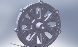
I did a 90:1 design already but it's too big & I'm going to make a 40:1; I'll post a picture later 8)
 
I'll try to get hold of some EN24 to make the bits. The trial one will be 5mm thick (each "wobbly thing")
Here's a picture of the 90:1
cycloid2.jpg
I won't water jet it, mostly because the water jet place is 15 miles away instead of 100yards, but also because in my experience they're less accurate, and kerf taper and exhorbitant prices. I don't have high expectations of this :)
The laser place can do 26mm steel, but at that thickness the cut is none too accurate any more...
 
Laser can cut up to 1" steel.

source: we do it every day ;)

works great for stainless too, mild steel gets the best finish typically. there is usually a bit of angularity to the kerf, this becomes more apparent with thicker material... of course you could just cut all the gears on the same sheet then alternate the orientation (face wise) to cancel out the angles. with a properly configured laser you can get some REALLY good surface finishes... like glass. CO2 lasers are good, fiber lasers are best.

accuracy wise, .002-.005" is a reasonable tolerance depending on material thickness. tighter tolerance than that requires machining (or, a wire EDM, if you wanna spend big bucks)
 
They cut steel with oxygen, the steel itself burns giving effectively a flame cut. I think they do stainless up to 6mm or so, powering through it with nitrogen. Al they can only do about 3mm, it conducts heat away so well it's really tough to cut. They can't do copper at all (but I think that's what the CO2 laser mirrors are made of). I'd guess the harder steels are not too different to mild steel under the laser (?)
Just looked at tangentdave's website - WOW nice looking stuff!!! I'm looking at trying a "homebrew" similar thing less than a quarter his power level though. It will be very interesting to see how (if) it works :?
 
Aluminum we do 3/16" and 1/4" no problem on the laser (but prefer to cut from big sheets on CNC router which is more cost effective).

hard steels will definitely be more limited on thickness than mild steel, but we don't cut any ferrous materials besides mild steel and 304 stainless sheet.
 
They might not last the longest, but gears are often made of much softer materials like brass or various polymers.
 
laser place said 5mm en24 no problem.
Now I have to find some.... Plate only seems available down to 10mm. Looks like I'll be asking for a 5mm length of a 150mm square bar... :?
It comes annealed (so its workable) - should I harden it (quench from red hot)(after I've made it work....)
 
I like this idea.

Is 5mm thick enough, or do you plan to pin two pieces together to double stack them for 10mm thickness?
are you going to run it with lapping compound to polish the pieces in, or just run it as it comes?

If you're running properly sized steel sprockets, you should not have to harden them. If they're undersized for the power, you can try case hardening them, but you'll probably just warp them from the heat. Heat treating stuff is tricky, and gears are especially tricky because they come to a point on the edges, but are thick in the middle and ring areas.
 
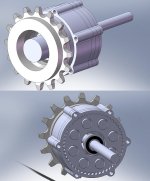
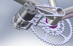
I guess I'll be making the thing below. I bunged a 16T freewheel model in about the right place to give an idea of scale. 2nd picture has the back off so you can see the innards. The actual gearbox is incredibly small, most of what you see is a ginormous dual row bearing to cantilever the chain pull on the freewheel...
Mrdude there are 2 5mm thingies in there, sort of opposite each other to cancel vibrations but working together. It does look like quite a handy way to electrify a pushbike.... I fancy this with something like an alfine/nexus 8 speed hub gear.
IF it works of course..... Yeah I was planning to use a dab of fine grinding paste to run in the cycloid things, but it all depends on what they come out like (which is waiting for the steel now)
If I need to, I can beef it up and cancel the theoretical remaining dynamic vibration simply by adding 2 more stacked cycloid stages.
The 2-wobbler design can be statically balanced but not dynamically; it seems logical therefore that a 4-wobbler will be quieter.
cycloid50.jpg
 
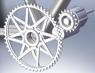
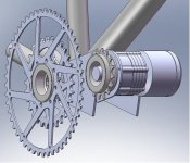
getting way way ahead of myself & thinking about installation - textbook mid-drive......
The motor is a bit long so primary reduction is 3mm pitch toothed belt (that's 30 quid motors for you...)
installation.jpg
 
EN24 in 5mm thickness is proving hard to get so plan B - make ordinary mild steel parts then case harden
Asked a "nitriding" firm to quote - WOW £76 + £8 p&p. All +VAT(20%) time for plan C
Weld up into a steel box with hair, fingernails, charcoal & a little bit of pee then heat in the forge to 900degrees for half an hour

There's always an engineering solution :)
 
Oh yeah, I found an old 6354 outrunner, the gear is now 40:1 with 4 wobbly things all 4mm thick, rather hoping it works properly now!! it's looking pretty neat
installation.jpg
 
Hopefully we'll see the lasered gears, rings and output spider tomorrow.
If you don't see a photo you'll know it hasn't happened.... fingers crossed

The assembly with a chunky outrunner looks good; should be a low cost DIY alternative the "tangent" linked above. The laser cutting will be £30 or so, bearings a bit more and the outrunner was also around £30, much like this one on hobbyking (which is now £45). This motor is listed as over 2kW, and will certainly do 500W or so continuously.
motor.JPG
Mounting brackets would be more laser cuttings, probably another £30
My control system uses a cheap RC ESC, made usable by a little avg microprocessor board. It needs a speed signal to work & I was going to get that off a magnet on the gearbox output freewheel + hall sensor. I included a battery current monitor on this board as well as hall throttle signal interface. It won't pull from zero speed but seems OK after a turn of the pedals and down to low speeds thereafter. All up weight should be just over a kilo
 
Laser work not ready. But I did just pick up a bike that someone had thrown away.... This has been painted yellow (including the tyres and chain) for use as a "decoration" when the tour of Britain went past last year. It's a nice looking steel frame, seems to have quality lugs & braze-ons for vee brakes. I'll replace the wheels and get the fattest tyres that'll fit. I'll keep the rear derailleur to 7 or 8 speed so I can use a relatively chunky chain. So if this gearbox works don't be surprised by the awful bike it appears on...... :)

Note design CAD says allup weight of outrunner + 40:1 reduction gearbox is 1.24kg
 
Made the input shaft this afternoon, lots of messing with 4 jaw chucks and dial gauges...

nearest eccentric is smaller diameter to allow assembly :)
+ I just bought all the ball bearings
 
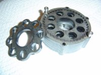
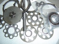
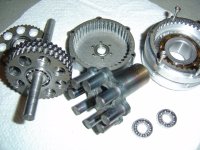
YES you can laser cut the gears - remaining question is how well do they work....
Meanwhile I'm waiting for bearings and on the lookout for a chunk of aluminium to convert into swarf (and a big output bearing housing)
DSC01630.JPG
 
It has the potential to make a compact and lightweight 1 to 2kW mid-drive machine for around £200. It's now all down to how efficient and/or noisy it is. The engineering is nothing special, some turned parts and some lasered parts. If it looks good I'll zip up the dxf's and the drawings & include 'em on here. If it sucks I won't.... :)
 
More machining done. I'm going to have to have a third attempt at the input shaft with eccentrics - the eccentrics are just too eccentric... Everything else looks OK for now :). Anyone copying this - laser 2 output spiders, one to weld the drive spigots onto, the other as a throwaway jig to make sure they weld on straight...
DSC01632.JPG
 
While I'm posting pictures - more recent installation imaginings.....
installation.jpg
BTW if anyone's interested, the pressure angle on the cycloidal "teeth" is 28degrees, a bit more than yer average gears (20degrees) so it's probably a bit less efficient for that reason if no others. That seems to be as good as you can get it. There's also a bit of sliding going on between the wobbly things and the output spider drive pins.
 
Back
Top