Can you laser cut cycloidal gear reduction parts?

awesome bob, can I come round and have a go when done?
 
Sure thing Andy, hopefully it will be sooner rather than later.
The bigger (5mmx60mm) cycloid stack came out of the laser place yesterday - finish not as good as the 4mm but still rolls ok
Bob
 
Noddy electrics assembled - first spin of mechanics. Generally good, not too loud. The assembly 'twitches' a bit, I may need to beef up some cross bracing in the mounting. Motor draws 3.9A off load. Gearbox warms up by a barely perceptible amount - something to keep an eye on. First I'll put more oil in (the black dot in the middle of the end of the output shaft is the plug from the end of a biro sealing the oil hole......
[youtube]mPVVfh3aBrE[/youtube]
 
Sorry not much activity on this. Anyway I made another slightly larger one, still 40:1 ratio but this time 60mm "working" diameter.
On this one I put needle roller bearings on the output drive spider; here it is partly assembled.
The laser cut parts you see there cost just £25, the bearings somewhat more.....

It still has the 4 rotors for dynamic balance, but this one should be slightly more efficient with the roller bearings. Provided they hang together (those drawn shell rollers are expecting to be forced into a tight hole, not roll round the inside of a bigger one)
PS - just bought a block of ally for the output bearing housing off ebay for £11, and a little stash of neodymium magnets to measure gearbox output speed
 
Gearbox above is assembled, running in oil, smooth as you like. Reason for post: I found some suitable motors on hobbyking, so I bought a couple (the motors in this class always seem to be on "backorder"...). The motor I have on the bike is a scrapper really, and I have a 2nd gearbox now. 2 motors with kV = 195, 63mm can, motor 54mm long, cost £25 each, + a load for delivery. It's all coming together, I should be able to get the bike going with the Arduino based throttle interface over the next couple of weeks; I'm looking forward to seeing how it behaves!
 
Nice work Bob, it's rare to see successful DIY cycloidal gearboxes. You may be the first on ES.
 
Hardware together; I'll build the bike up with this setup rather than the dodgy motor above.
Having a pukka motor makes the assembly much quieter.
The battery current display option on the "speedo needle" is pretty cool :)
DSC01655.JPG
 
I put this bike together today with a single 6s LiPo and went for its first ride.
It was reasonably quiet actually (even though it still had the old motor with the off-balance bell).
It broke the chain after 100yards or so, I think the bottom bracket bracket isn't strong enough in torsion so the motor twisted and the chain tried to climb off, it actually snapped a link.
The chain tensioner is not in line with the chain; I think I need to do this too (it's probably the main fix) - being off line creates the twising force.
So: some strengthening to do but while it worked the feel was nice and the noise reasonable, much quieter than my other bike with a smaller outrunner. The noise (buzz) is related to motor speed not load torque.
 
Sorry, it's cold & dark now & I've been busy at work.... I'll beef up the mount & try again - I suspect I've probably tried to keep it all too lightweight... None of the "trellis" buckled but the motor/gearbox sort of twisted so I'll have to add an extra thing to prevent "lozenging". Give me a few weeks :) The electrics all seemed pretty sound. And the gearbox had no trouble at all with enough stress to snap a bike chain.
 
Looking forward to more updates...eager to hear the sound when it's running properly!
 
[youtube]h03OPndJAu8[/youtube]
First reasonable length trip with this. Worked pretty good (so did the RC servo dashboard gauge - this was supposed to be showing battery amps but it was a bit random - bit of work needed on the arduino code)
The gearbox was clearly very lossy, you could actually feel it was warmer than ambient, and the power was not in the right ball park; but overall not too bad for the first punt. I gave Andy (whereswally) the 2nd prototype to have a play with; that has roller bearings in so I hope it's rather more efficient. You could feel a buzz through the pedals and you can hear the noise it makes - it's actually not too bad, (the noise) I never felt embarrassed to wind the power on. I think the 4 rotor design has worked quite nicely. The output double row bearing is well on top of the job and the bottom bracket bracket is now clearly strong enough now I put the extra brace on the motor/gearbox clamping plates
 
Deafcat said:
Laser can cut up to 1" steel.

source: we do it every day ;)

May i ask whats the power output of the laser? We got 3.2 kW(max) laser machine and things really go bad (welding problems) over 15-16 mm black steel plates and 20 mm stainless. Aluminum (and simmilar) plates go with no problems 15 mm+ but rough edges appear (needs a bit of scrubbing). I got no experiences with lasers, other than this 1 machine. Just personal interest.
 
Finally got said break in my 3d printers schedule (printing mpcnc parts at the moment) I managed to undo. Bob's taper lock and release the motor from the gear box, this allowed me to undo the wobbly mount, scan it on my flat bed printer and fab up a complimentary spacer which aligns up the heads of the bolts from both the gearbox and the motor, the result being not more wobble. I forgot to take pictures but here is the finished result. IMG_20170212_125745.jpg
Annoyingly mount had no symmetry so was tough to perfectly reverse engineer. Grrr.
 
IMG_20170228_222651.jpg
My first attempt at a hall sensor mount for this motor using a plastic printer. Will need refining but not much.

Sent from my ALE-L02 using Tapatalk
 
made a second attempt at this last night, improvements were;

1) opening back up the vent holes

2) increasing the gap between the nut bolt connector so that it doesn't fuse together so hard on printing. This time it fused but could use a cold blade to cut the plastic apart for a cleaner quicker finish (the picture above the plastic needed a hot blade to cut apart the opening which messed it up a bit).

3) No need to drill the plastic either to get a hole for the phase wires now either and there is some scope for rotating to get better calibration of the halls to the phases.

hopefully have a go at testing with a s06 controller fake sin wave (pseudo torque) by the end of the weekend.
 
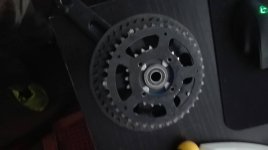
Made more progress today, rebuilt the bottom bracket with new bearings and two of the three brass spacers bob and I made. Also came to mount the rhs crank and found the chaining to the motor was so close to the rear lower stay that when a chain is on it but facing toward the motor it would wear a hole through it. Luckily I found another perfect unused chaining with the same bolt pattern in my parts bin. Problem was bolts were 6mm holes on my new smaller chaining are 8mm. Solution print a spacer and 4 bolt spacers.
IMG_20170304_165748.jpg
new crankset with plastic printed bits
IMG_20170304_165829.jpg
old one on top for reference
 
IMG_20170304_174212.jpg

IMG_20170304_174231.jpg

So you can see this ain't gonna work without some fettling.

Just had another look at this offered up on the bike, next problem chain line well out of whack. Searched the parts bin again found another large chain ring which i changed off my dahon cadenza solo from 44t to 53t years ago. This spare 44t with 5 bolt pattern can be attached to the spokes of the existing chain ring if i drill carefully some holes and use spacers to bring the chainline back into line with the rear cassette, going to maybe take this to bobc's rather than drill it myself, chances are that i will proper frock it up if i try. I could print a jig on my printer and use my pillar drill. hmmm we shall see.
 
So I had another idea for mounting the motor which is for it to go between the shock and the rear wheel. The issue with this plan is that on the non-drive side the rear stay pokes out beyond the bottom bracket. To get around this I need a bearing cup which is a bit longer.

Sent from my ALE-L02 using Tapatalk
 
IMG_20170318_215111.jpgIMG_20170318_215119.jpgView attachment 2
Here is today's progress, using m8 bolts turned by bobc on he lathe, some halfnuts and some nylock nuts we have a crank freewheel. Also my threaded rod and nuts have arrived to complete the motor mount but I now need to design my custom plastic bits to protect the frame and the chain tensioning device. My other project mpcnc has been taking up lots of time too but things are coming along now.
 
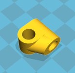
coupler piece for bobc cycloidal drive.jpg
this is the snagit of cura, the stl file exported from the cad program.

This coupler is to replace the alu tube bobc uses to tension his up. I figure I can achieve the same thing with more 6mm threaded rod more evenly using couples of these all along, two bars may do the job but it wouldn't be difficult to fabricobble more if the strength of plastic was an issue keeping the chain tight
 
Back
Top