Changing the LVC in a 72v generic controller

wesnewell said:
Do you understand that a 72V SLA battery pack in good condition will charge to over 80V? That's why it shouldn't be rated as a 72V controller using 75V fets. These aren't batteries, and the ratings aren't nominal ratings.
In my experience, peak voltage of an 72V SLA bank settles quickly to around 78-79V. I've run experiments a couple of times taking regular readings during the discharge of a battery bank, then plotting it out to get a discharge curve. The discharge curve of a lead-acid cell typically goes something like this:

batterynormcurve.gif


Though peak charge of a nominal 72V bank may just crack the 80V mark, voltage rapidly drops and plateaus, with most of the discharge spent somewhere between 78 and 72V (though obviously you can discharge them further if you really want). It therefore spends hardly any time in the 80-84V window that that my LiFePO4 occupies through most of its cycle.

I've already explained ad nauseam how ratings given to components are ultimately always nominal, because the rating always makes certain assumptions about how the component is being used, what the operating temperatures are, and countless other factors.
 
The Mighty Volt said:
@Wesnewell
I made a mistake. I have I407 Mosfets in mine, rated for 75v, in a 48v rated controller, which is acceptable.

The ratings are only nominal.
Yes. Exactly.

The Mighty Volt said:
For instance, a 100v rated capacitor is rated to 100v, give or take 10volts.

So it could be 90 or it could be 110.
Yes. Exactly.

The Mighty Volt said:
These controllers should be a cheap platform for us to work off.

Nothing more.
Yes. Exactly.
 
auraslip,
Is it possible for you to fix this link?
Thanks

auraslip said:
So I ended up installing a 2.2k resistor rather than the SMD resistors. Some napkin math calculation says it should hit LVC near 37v (or 2.3v per cell for 16s).

I've tried to figure out how to do regen on this controller, but I've got nothing. I've figured out how to activate the brake through the high line. Seems a bit weird to run full battery pack voltage to the handle bars but what ever.

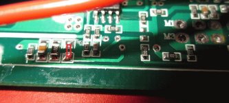
Here is the resistor wrapped in heat shrink.
 
auraslip said:

The picture is perfect and by reading and reading and reading, one can finally figure out exactly which SMD you removed & which points you connected the resistor to. I thank you for all the work and now understand exactly what you have done. It would be great for the next newbee who stumbles onto this thread, if a summary was edited into the first post.

I am a bit concerned with the use of a pot on the board. You may be introducing unwanted L/C into the circuit? I don't have a clue if this is so, just wonder?
Thanks again,
 
auraslip said:
I posted the relevant part on the first post. what is L/C?

In my view, that makes this thread infinitely more valuable. You went to a lot of work figuring out how to lower the LVC and now the next fellow can take full advantage of your labour. Perfect. :D I wish all threads where in reverse chronological order, with the conclusion at the beginning.

L is inductance, C is capacitance. Every additional component induces some L/C. The length of the leads on the added resistor could make a difference to the functioning of the circuit, when compared to the SMD it replaces. I do not know if this has any negative effect on the controller, just a caution. It is just good practice to keep lead lengths to a minimum. Mounting the resistor vertically, by making a 180* bend in one lead, is an option. :mrgreen:
 
Gordo said:
I wish all threads where in reverse chronological order, with the conclusion at the beginning.
While it is not the default, you can do this if you wish:
http://www.endless-sphere.com/forums/ucp.php?i=prefs&mode=view
"Display post order direction:" change to "Descending"
and it will now display newest post in a thread first, with the first post in a thread on it's last page at the bottom.
 
Perfect AW. Thank you very much.

I do think it is a great service to all to summarize the important points in one post as auraslip has done. Sometimes you can hunt a long time before you put the details together in to a meaningful whole.
 
Hey Auraslip, can you share with us some of your napkins math calculation ?
I want to run this cheap controller at 24s, so I'd like to increase the LVC to get the regen to work at higher voltage.
 
PeeHell said:
Hey Auraslip, can you share with us some of your napkins math calculation ?
I want to run this cheap controller at 24s, so I'd like to increase the LVC to get the regen to work at higher voltage.
I wouldn't do that if I were you. These controllers use P75NF75 FETS, which are only rated for 75V and are already being slightly overclocked by a 72V SLA bank, which will run as high as 80V fully charged. If you run this controller on a 24s pack (mine is a LiFePO4, nominal 76.8V) it runs way too hot and this happens:

pr03-1600x1200.jpg

http://zenid10.wordpress.com/2011/09/03/meltdown/

I used my cheap controller for a few weeks while my Lyen 12-FET was being repaired. It lasted pretty well, but when it stuttered a couple of times I took a look at it and realised that it was starting to melt! Used gently you can just about get away with it, but they run very hot.
 
Not this again.:) Both my controllers had 100V caps and fets, and run cool with a 24s lipo pack at 100V charged. So it depends on which controller he has. AFAIK only the 2 headed wire bundle controllers had 75V fets. Of course one can check when they open the controller to change the lvc. I haven't changed lvc on mine and run 18s and regen works perfect on it. Looks to me like you just need to change the value of the 3 resistor bank to change lvc. Maybe put a pot or 3-4 poll switch across it with different value resistors so you can easily change it.
 
wesnewell said:
Not this again.:) Both my controllers had 100V caps and fets, and run cool with a 24s lipo pack at 100V charged. So it depends on which controller he has.
I'm pretty sure he's talking about the cheap, Hua Tong controller that is the subject of this thread.
 
The original post was for the same controllers I have. You can see the 100v caps in the very first post. It's not the double headed one you had with 75v fets which is totally different looking even form the outside.
 
wesnewell said:
The original post was for the same controllers I have. You can see the 100v caps in the very first post. It's not the double headed one you had with 75v fets which is totally different looking even form the outside.
I did have a double-headed one, but the one I opened up and took loads of photos of and tried to change the lvc on was a typical, single-headed one (one of the first batch of ten I got last year):

pcb1-1600x1200.jpg


The FETS on mine were definitely 75V ones. Evidently they're not always the same, and maybe more recent batches are different. Something else odd I've noticed through three batches of these controllers is that the current rating on the sticker has been dropping: In the first batch they said "45A", in the second batch they said "40A", and now they say "38A"!
 
so you raise the resistance on that resistor and you get a lower LVC, lower resistance means a higher lvc?
 
ian.mich said:
so you raise the resistance on that resistor and you get a lower LVC, lower resistance means a higher lvc?
Heck if I know. I'm so confused with all the drilling, jumpers. etc. I'm not sure any more. I've got mine apart now and am about to install a 0-11k variable across the last smd resistor on the left marked 222 (2200 ohm) and see what I get when I lower the value across it.
Ok. Lowering resistance across that resistor didn't do squat for raising lvc, so installed it in the far right blank smd resistor spot and started cranking it down until the motor wouldn't run at 86V. Had battery hooked up through the spark arrestor resistor and when I hooked it direct for a little over 95V regen braking started working again, so I guess that's it. Rough guess of added paralleled resistance is about 3k ohm.
 
Just a followup. LVC cut in at 94V so I had to adjust the VR to a higher setting. I'm now guessing somewhere ~ 5K ohm would be close to what I want, which is 88V lvc. But anyway here's where you want to add a resistor to up the lvc.LVCmod.JPG
 
parajared said:
Is there a way that you could just cut a wire or something and completely disable LVC?
I'm not sure why anyone would ever want to do that, but you could remove the resistor next to the one I added, leaving 2 open spots for resistors and LVC will definitely be lowered, but I don't know what it will be. IIRC it's a 2200 ohm resistor. Easy enough to take off and see. Although not knowing what affect it will have, I'd probably put a 5-10k in it's place and see what lvc ends up at and go from there. There's really no need to completely disable it. Maybe replace it with a 0-12k var so you can adjust it to whatever you want.
 
I bought a couple of controllers that were supposed to be 36v but turned out to be 72v controllers grrrr :twisted:

Hooked up one of them to the programming cable to PC and changed the LVC back to 36v.

The other one I can not do this as I gave my programming cable to someone and it's now gone, would love to just cut or does older something to have no LVC....that's what my BMS is for.
 
I'm not sure why anyone would ever want to do that, but you could remove the resistor next to the one I added,
Perhaps I am misinformed. LVC is just to protect your batteries right? If you have a little voltage readout like this one zip-tied to your handlebars, there is really no point in having a LVC.
Does the LVC serve another function other than battery protection?

3176B%2B0ehnL._SL500_AA300_.jpg
 
parajared said:
I'm not sure why anyone would ever want to do that, but you could remove the resistor next to the one I added,
Perhaps I am misinformed. LVC is just to protect your batteries right? If you have a little voltage readout like this one zip-tied to your handlebars, there is really no point in having a LVC.
Does the LVC serve another function other than battery protection?

3176B%2B0ehnL._SL500_AA300_.jpg

When the LVC trips the controller is inoperable, an LVC that is too low ends up killing your batteries...an LVC that is too high shuts the controller off before the batteries have been discharged. Capishe?
 
[
When the LVC trips the controller is inoperable, an LVC that is too low ends up killing your batteries...an LVC that is too high shuts the controller off before the batteries have been discharged. Capishe?

Yes,
but who cares. I mean really why would we want this at all? Just use your brain and stop riding when you see yourself reaching the voltage cutoff point on your display. My only concern is that this "feature" is linked to something else in the board. You still want the controller to work after chopping the bugger off.
 
Back
Top