Charging 16s using 2x 8s chargers - what have I done wrong?

dnmun said:
we should be able to fix the shorted charger too. i suspect the isolation mosfet on the output is burned so just replacing that should make it work again.

Indeed you're probably right.

1HJh37w.jpg


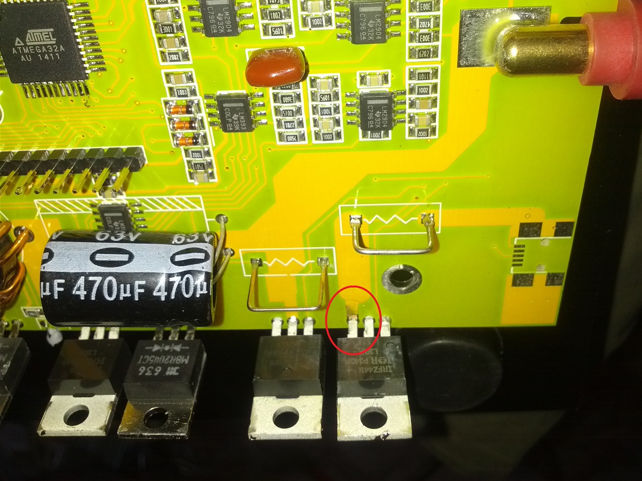
At the very least this trace is blown. The fet it's connected to goes to the negative lead of the output. It's a irfz44n, and the charger uses two of them. One at the input, one at the output. So I figured between four fets, I'd hopefully have two working ones, but that doesn't seem to be the case. I tried testing the fets from my first blown charger, using a youtube guide that showed how to use my dmm's diode test setting to test the fet. That doesn't seem to work though, none of these fets will turn on. What are the chances I blew both fets AND a trace on the board?
 
it is not a mosfet, it is a dual cathode schottky diode that is the overheated part in the middle. you can buy them on ebay for cheap. go google the part number MBR2045CT, and you can use your diode tester to see if it is still intact or shorted.

the mosfet where you circled the source leg you can test also with the diode tester to see if it is bad. google the part number on it too.

to test the mosfet with the diode tester put the red probe on the source leg and the black probe on the drain leg or tab. i think that is a pchannel mosfet so it show open circuit, but it may be an nchannel mosfet and you will see the forward bias of the body diode. if it is shorted it will be zero. reverse the leads to confirm the body diode too.
 
dnmun said:
it is not a mosfet, it is a dual cathode schottky diode that is the overheated part in the middle.

What makes you think it's overheated? It looks fine to me. It's a different colour than the surrounding fets, but I think it's just a different type of metal. Looks like stainless.

Anyway, tested the diode by putting negative lead on the tab and testing the outside pins. Both pins give more or less the same reading, 0.163 and 0.162. So I think that's normal.

As I mentioned in the above post, the fet is an IRFZ44N, an n-junction mosfet. Being that it's on the negative side of the output, that makes sense. Earlier I had tested these with the wrong polarity. Now I realized I have a working fet, so I replaced it, repaired the broken trace, tested, and I'm back up and running with two working chargers!

I just have to put a disconnect between b8+ and b9- to charge.

Thanks for all your help everyone!
 
Alright, so here's a really stupid question.

I have a 72v-to-12v dc-dc converter in my bike, to power the 12v system including brake lights etc. This converter is capable of 300w, and it's never got more than a 50w load on it.

So... How stupid would it be for me to charge half my battery... FROM my battery?

I would run one turnigy charger off the SLAs in my trailer, and run the other off the bike's 12v system. I have no reason to believe this wouldn't work, however, I'm no sure what effect it would have on one half of my battery charging the other. Surely it would take longer overall, since I'm still only charging at 150W, but at least it would be isolated, and I could charge both halves of my battery without having to disconnect anything. In fact, I could even charge while driving.

On the other hand though, half of my battery would be getting more wear than the other half? I think?

Thoughts? Opinions? Am I retarded? Or genius?
 
inedible said:
So... How stupid would it be for me to charge half my battery... FROM my battery?
To make the consequences clearer, let me ask you this:

Why would you want to take your full gallon jug, pour some of it into another jug thru a leaky funnel, then pour that back into your gallon jug with another leaky funnel, so that you don't even have a full gallon jug anymore, having spilled a fair bit of it out during the transfers?
 
i still do not get why you decided you have to use these balancing chargers. it would be so much simpler to just bulk charge with a BMS and use a DC/DC boost converter. simplest, cheapest, most reliable, shared ground so no shorted outputs. duh.
 
dnmun said:
i still do not get why you decided you have to use these balancing chargers. it would be so much simpler to just bulk charge with a BMS and use a DC/DC boost converter. simplest, cheapest, most reliable, shared ground so no shorted outputs. duh.

I've been charging this pack for a year now using a bmsbattery.com "alloy shell" 1200W charger. I had a bms at one point but I broke it. The cells stay pretty balanced though. I think what they say about LiMn2O4 "self-balancing" is true.

The whole point of this exercise though is to charge off solar. I have a 12v source to charge 16 lithium cells, so I figured these turnigy chargers would be my best bet. Couldn't find any bulk chargers that run off 12v when I looked.

See, I've decided to drop everything and go on a crazy adventure, driving across the country with my electric scooter. For the most part I'll be charging off grid power, but I need a solar setup in case I get stuck somewhere. Hence the chargers that run off 12v.
 
" Couldn't find any bulk chargers that run off 12v when I looked."

did you look on ebay for a 12V boost converter to get you to the 67V? why won't your solar charge up two 12V batteries in series so you could use the 24V boost converter. that is all they use in the balancing chargers. plus they are only $40-50 on ebay.
 
I figured these balance chargers would be more robust. They do constant current then constant voltage mode, they have all kinds of overcharge and undercharge protection, temperature sensors, etc. They can show me the individual voltage levels of each cell at a glance, which is nice. Plus if/when my cells ever get unbalanced, I can balance them.
 
I have in mind a similar approach for my 16s packs. Do you guys think that charging with 2 chargers fed by two distinct power supplies is safe?
 
Back
Top