I ordered an ECityPower "smart" BMS from BMS Battery on Aug. 17, 2010, with my custom voltages, currents, etc.
It shipped DHL on Aug. 19.
It arrived in Ontario, Canada on Aug. 23.
The BMS and a few extras were appropriately and safely packaged.
There were no hidden fees.
The BMS arrived with the battery wiring harness, with 13 black leads. And there is what is likely a heat probe coming off the board for three inches. The board is a 12s board, and is nice and small at 2.2" x 3.2" (sorry for decimal, calipers where handy).
On the ECityPower site, the photo of the board shows a three pin connector in the upper left of the board. There is no such connector on my board. The only negative seemed to be grossly excessive solder where they added the FETs, but a friend told me that helps with heat management. To attach the power leads, I can either heat the solder up or drill through the solder to the hole in the board and bolt the leads to the board. Under a stereo microscope, we can see that the board was not in a clean environment, with debris and lots of spare solder drops, but all of the connections appear good. From the amount of solder used for various components, it appears that the board was built with the surface mount devices first, and then at a later date, additional components were added by hand. This fits with the customizing available when ordered. There are clamp marks on the power FETS so we know the feet were held to the board contacts when soldered and the FET was heat protected during soldering. It's not a top quality board or build, but my friend assures me that the construction (design unknown) is perfectly adequate to the task. There are numerous testing contacts on the board, and one can see an intent from a probe on each, so it appears that the board did go through QA. There is one place where we can see that something sharp was used to remove trace copper that was a fault between two traces. There are a few jagged piece of copper sticking out from each trace towards the other, but from the testing probe indents, we assume that it did pass QA after this correction. This repair was done by cutting through the surface coating on top of the board & traces, leaving a white canyon line through the coating. This has not been resealed (should it be?). The opaque white of the scratched/cut away surface coating is surprisingly consistent with scratched Tung Oil; curious to know the dielectric properties of Tung Oil.
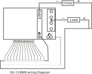
(~edit: speculation superseded by supplier's connection diagram)
From looking at another of the ECityPower boards, it appears that they like to tie together: battery +, load + and charger +. Then ground both the charger negative the load negative each through their own power FETs to battery negative.
From the board nomenclature it appears that the cell wiring harness has a lead go to the positive of each cell, with an additional lead we guess must go to the bottom cell's negative. On the board, this bottom lead is tied through a small resister to what we think is where the load negative ties into the top of the load's power FETs.
So it appears that the board attachments are:
In the absence of confirmation of the above, I'm rather hesitant to wire it up to the cells.
Does anyone have any experience with the ECityPower Smart S5-13 BMS?
It shipped DHL on Aug. 19.
It arrived in Ontario, Canada on Aug. 23.
The BMS and a few extras were appropriately and safely packaged.
There were no hidden fees.
The BMS arrived with the battery wiring harness, with 13 black leads. And there is what is likely a heat probe coming off the board for three inches. The board is a 12s board, and is nice and small at 2.2" x 3.2" (sorry for decimal, calipers where handy).
On the ECityPower site, the photo of the board shows a three pin connector in the upper left of the board. There is no such connector on my board. The only negative seemed to be grossly excessive solder where they added the FETs, but a friend told me that helps with heat management. To attach the power leads, I can either heat the solder up or drill through the solder to the hole in the board and bolt the leads to the board. Under a stereo microscope, we can see that the board was not in a clean environment, with debris and lots of spare solder drops, but all of the connections appear good. From the amount of solder used for various components, it appears that the board was built with the surface mount devices first, and then at a later date, additional components were added by hand. This fits with the customizing available when ordered. There are clamp marks on the power FETS so we know the feet were held to the board contacts when soldered and the FET was heat protected during soldering. It's not a top quality board or build, but my friend assures me that the construction (design unknown) is perfectly adequate to the task. There are numerous testing contacts on the board, and one can see an intent from a probe on each, so it appears that the board did go through QA. There is one place where we can see that something sharp was used to remove trace copper that was a fault between two traces. There are a few jagged piece of copper sticking out from each trace towards the other, but from the testing probe indents, we assume that it did pass QA after this correction. This repair was done by cutting through the surface coating on top of the board & traces, leaving a white canyon line through the coating. This has not been resealed (should it be?). The opaque white of the scratched/cut away surface coating is surprisingly consistent with scratched Tung Oil; curious to know the dielectric properties of Tung Oil.
(~edit: speculation superseded by supplier's connection diagram)
From looking at another of the ECityPower boards, it appears that they like to tie together: battery +, load + and charger +. Then ground both the charger negative the load negative each through their own power FETs to battery negative.
From the board nomenclature it appears that the cell wiring harness has a lead go to the positive of each cell, with an additional lead we guess must go to the bottom cell's negative. On the board, this bottom lead is tied through a small resister to what we think is where the load negative ties into the top of the load's power FETs.
So it appears that the board attachments are:
- the harness, attached as we assumed above,
- load negative to board,
- charger negative to board,
- battery negative to board.
In the absence of confirmation of the above, I'm rather hesitant to wire it up to the cells.
Does anyone have any experience with the ECityPower Smart S5-13 BMS?
")