Controller Wire labeling help

raz1972

1 µW
Joined
Jun 4, 2016
Messages
3
Hi there.. I'm new to the forum and new to ebikes.. I'm in the process of getting parts to build a commuter for myself.. I purchased a controller and hub motor from a seller that was about to move overseas and he had said he would send the details for the controller manual or wiring diagram.. but have not heard back.. I know the basics but i'm just trying to see if anyone here would know what some of these cables connector should be..

i know most of the connectors on the left.. Motor, HALL sensors, brakes etc.. but the three on the right.. one has a six (6) connector.. from reading forums and sites.. black, green, red (sometimes yellow) is throttle.. ?? but i'm not sure what the others are.. if anyone has a similar setup and is able to give me some indication, i would really appreciate it..
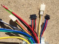
IMG_5208.JPG


Kind regards
Noobie

Raz
 
fechter said:
What is the model of the controller? There are lots of variations in the connections.

Thats the problem.. there are no labels on the controller box at all.. been trolling the net to see if i come across any controller pictures that are similar but nothing has shown up..
 
That's going to be tough.
I'd guess one of them should go to the brake switches to cut the power.
One may be a PAS sensor, which you could leave disconnected.
The 6 pin one probably goes to a display unit of some sort, which could also be left disconnected.

Other possibilities are:
a 3 speed switch
cruise control
anti-theft
battery voltage indicator

If you apply battery power, measure the voltage on the pins to get an idea what they do. Measure with the negative lead of the voltmeter going to the battery negative. Look for wires that are connected to battery voltage, ground, and ones that have 5v on them. It should give you a clue.
 
If it were me, I'd open it up and get pics of the circuit board itself, showing where the wires go on the top side, and the silkscreening/etc on the bottom side, which might be similar enough to another controller already figured out here on ES to figure out what those wires are here.


Also, you might post pics of the actual controller box, even though it has no labels, as someone might recognize it and be able to help.
 
It has special wiring. It's not like all the common ones. You will have to open the controller to show where all the wires go to identify which is the ignition wire. You need to identify and connect the ignition wire before you'll get any voltage on the other wires to see which is which. My guess is that the seller knew that it was a special, which may make it difficult to install it as a standard one. It might even be a torque sensor controller or something like that.

Where does that purple wire go?
 
Here are some internal pictures..
IMG_5210.JPG
IMG_5211.JPG
The Purple cable goes under the PCB..
View attachment 1
IMG_5213.JPG
From just looking at it.. the brakes connection is part of the blue cable with white strip.
 
Need another photo where the red, blue and yellow wires are soldered. Can you hold up the wires to show the markings on the board and try and get it clear enough to show the tracks on the pcb? We need all the way from the corner to where the writing on the edge says something like SX1411.

From what I can see, it looks like the red is battery voltage and so is the blue. The yellow is the ignition wire. I need that photo to confirm.
 
Good idea.
On the circuit board where the wires attach, there are some labels. If you read those (or get readable pics), you have a better chance at figuring out what they do.
 
Back
Top