Controller Wiring Help

bike4life

10 W
Joined
Apr 10, 2020
Messages
82
Ok so i am thinking about ordering this controller cause my old one does not seem to work... I am installing this on a voliamart kit.

https://www.amazon.com/G%C2%B7PEH-1500W-Brushless-Controller-Scooter/dp/B08151BJ56/ref=sr_1_1?dchild=1&keywords=1500w+ebike+controller&qid=1591722263&s=automotive&sr=1-1

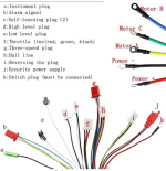
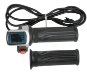
However, how do i wire this to a hand break. I dont see any wires that would go to the hand break. Also what is this switch plug (k)..... Also, my throttle has a lcd with 3 blue bars, and has 6 wires. (black,red,white,green,yellow,brown) The throttle in the picture has 3. How would i wire that and how would i know which colors go where.... My throttle also has a power button on it...
My throttle is attached below.


My original controller that worked was a voliamart 1500w controller... But i cant order that cause it would take 2 months to arrive on ebay. This one arrives in 4 days...
 

Attachments

  • Annotation 2020-06-09 130636.png
    Annotation 2020-06-09 130636.png
    98.1 KB · Views: 997
  • Annotation 2020-06-09 132133.png
    Annotation 2020-06-09 132133.png
    107.6 KB · Views: 990
E-brake is either d or e (low level plug or high level plug). If I recall correctly, most basic e brake cutoffs are low-level.

Most hall-effect throttles use three wires, +5V, 0V and a signal wire. The extra wires on your throttle are likely for the power switch and the voltage meter all sharing a common ground (0V, usually black).
 
That is your ignition wire, Chinese arent that fluent in english so they come up with some clever names themselves for various wires. Whats even funnier is reading instructions from any product, its a real laugh.
 
You can wire it directly to Power +, or you can add a switch to it connecting it to Power +.
If you use a switch, be aware that there are 3 ways a controller may act to this being "Off" but the battery plugged in:

1.) The power is off and there is no power drain on the battery at all, or is less than a micro amp. (I have only 2 controller out of many that acts this way. One of those is for a brushed motor)
2.) The controller is shut down, but there is a small power drain from normal power leaking across the Capacitors or other components. Usually in the .001 amp range. .001 amps on a 36 volt battery will drain 1wh of battery capacity per day. If you leave your drained 36v battery plugged in with just 30wh remaining, a controller with a .001amp draw when off will murder that battery if you leave it plugged in but "Off" for longer than 30 days. (Most of my controllers or ones I've worked on have been like this.)
3.) The controller is shut down, but there is an active resistor to pull the voltage down on the capacitors for safe storage, and it will pull up to a watt an hour. That would murder the above mentioned battery in just 30 hours. (My old Crystalyte Analog controller was this way, and I've had others. there is a post somewhere on this forum about an Infineon based controller with the circuit diagram showing this resistor, but it's been years, and I don't remember who's or what it was titled)
 
Hi
If its ok to jump in
I am sharing the same controller, can you please advise on the rest of the wiring ? For example what is Alarm signl? Security power supply? Instrumental plug?
Have much experiance with other controllers but the chinese englise is a killer..
Thanks !
 
Back
Top