Conversion of a Bultaco Sherpa

Thanks a lot. :thumb:
With that information I can work !

Do you think I can test the settings of the potentiometer on my desk, by connecting the dark grey wire and plus and minus?
And then running motor/controller/throttle.
If I watch the motor rotation speed by help of the kelly software, and calculate the secondary transmission ratio?
(I know the sprocket teeth numbers and the wheel diameter)
 
Do you think I can test the settings of the potentiometer on my desk, by connecting the dark grey wire and plus and minus?
And then running motor/controller/throttle.
If I watch the motor rotation speed by help of the kelly software, and calculate the secondary transmission ratio?

Yes, that is the best way, the pot is a bit twitchy. It is the way I done it with that kind of displays. (well not first time :lol: )
At the control screen you can see the rpms of the motor when the motor is connected to the computer/pad, just check it at 2-3 different motor speeds... If properly done it will not need more adjustments afterwards.
 
Since I am almost done with some work around the house (which had priority to the Bultaco build),
I was looking through the material I have collected until now,
and realized that I am still missing a key switch.

Any recommendations here?
(preferrably from Europe, in order to not waiting an eternity for the delivery)
 
Doesn't your Bultaco have a key switch already? If not, you can get a secondhand one at a breaker from a scooter or moped. It is just a switch so a hidden switch somewhere is also an option.
 
After a break, due to some family issues, I want to go on with my conversion of the Bultaco.

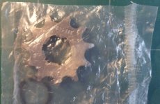
Together with the motor, controller etc., I had ordered two sprockets with 11 teeth. They sent me #428 ones.
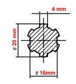
They fit the 20/16mm shaft (with 4mm splines), and came with circlips.
MY qs138-output-shaft.jpg
sprocket 428-11.jpg

But I want to use the original chain size, which is 520.

Therefore I would like to trade 2 new 428/11 teeth sprockets for two others in 520/11 teeth.
(Only inside EU-otherwise shipping costs would be too high, compared to item value)
 
Still not much progress-too many other things to do...

At least, in the meantime, I have received the #520 - 11 teeth - sprockets from an Aliexpress seller.
To my amazement, they are better than the 420 ones, which QS sent me.
Still a little play, but nothing compared to the miserable fit of the QS ones.

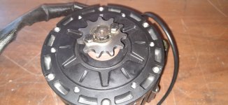
520sprocket.jpg

For some first tests, they will be OK.
For the final solution, I will see if can weld on a little material in the center hole, and file it down to a perfect fit.
 
I can not see perfectly in the picture what kind of screw grade they are but they look like 5.8 if so: that is not good. They need to be 8.8 at least for that application.
As well the head screw looks like it is going to interfere with the chain. I suggest that you use cylindrical hex socket screw instead that head is smaller.
 
_GonZo_ said:
I can not see perfectly in the picture what kind of screw grade they are but they look like 5.8 if so: that is not good. They need to be 8.8 at least for that application.
As well the head screw looks like it is going to interfere with the chain. I suggest that you use cylindrical hex socket screw instead that head is smaller.

Elektrosherpa said:
Thanks-thats a good point. :thumb:
Until now, I havent looked at the material thoroughly, just tried the fit on the shaft.
The screws are labelled "8.8", but I also have the impression that the screw head might interfere with the chain.

The bolts only need to clamp the retaining plate onto the sprocket but don't take any load. The plate is there to prevent the sprocket from sliding of the shaft. The load is passed from the splines on the shaft to the splines in the sprocket. So the bolts are more then fine in strength. And it looks as if not the bolt head but the retaining plate will interfere with the chain. So using Allen bolts is not enough but you should also file/saw the plate enough to not touch the chain.
 
Due to all things I have to do, progress in my conversion is kind of slow.

Only progress until now:
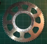
I have found a manufacturer, who can make a rear sprocket with 70 teeth, which fits my original rear wheel hub.
(70 teeth is the maximum he can make, so I will try with this)

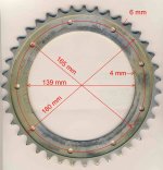
Here is a pic of the original sprocket (39 teeth):
RearSprocket-corr.jpg
 
While waiting for the rear sprocket, I am still pondering the battery thing.

My initial idea was to use lead acid batteries, 5 times 12V 30Ah in series.
Later, when I have built a 60V Li-Ion battery, these could be used in parallel in my camper van as additional storage.

Now I have come across some quite affordable offers on Ali, for example this one:
https://fr.aliexpress.com/item/32961812100.html?spm=a2g0o.store_pc_groupList.8148356.33.7113248eVJRaP7

I would be glad to hear some opinions about my initial idea, and about the offer linked above. Would this be suitable for my Kelly KLS7245N?
 
Yes, that battery looks quite reasonable for your application. And the controller will perfectly work with it.
 
My new custom made aluminium rear sprocket (#520-70 teeth) arrived today:

rear sprocket 70 teeth.jpg

From a German company, not really cheap (~100 € including shipping to France), but made exactly to fit the Bultaco rear hub, with the same recess in the center as my original sprocket, and the weight reduction holes adapted to the 9-hole-fixation of the Bultaco hub.
Company was quite unflexible concerning the shipping method, but their work looks good.
 
Another step done.

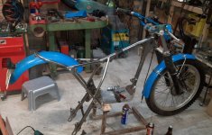
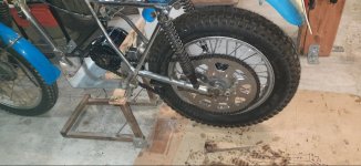
Removed all the combustion engine stuff:
Fuel tank, exhaust system, ignition coil, kill switch, air filter box, engine/gearbox with carburetor

Bultaco-Disassembled-06.jpg


In this foto you can see the color difference between the alu parts and the nickle-coated Reynolds 531 steel tubes of the Sammy Miller Highboy frame better than in reality...
 
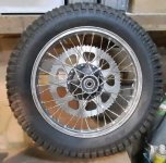
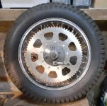
Meanwhile I put back the rear shocks, mounted the rear wheel with its big sprocket in place and put on a chain, in order to determine the exact position of the QS Motor.
Without knowing the motor position, it doesn't make sense to try finding places for the other items (battery, controller, DC-DC converter, main contactor, etc.).

Chain line1.jpg

The front fixing screw of the brake anchor rod and the chain oil outlet in the left swing arm need to be modified-they come too close to the big sprocket...
 
Mounted the display (which, by the way, I didn't have to tune - a test showed that the factory settings match pretty well my transmission ratio/rear wheel diameter), and prolonged the rear fender with a piece of aluminium sheet metal in the area, which previously was covered by the air filter box.

Today I started to make the motor brackets:

MotorBrackets1.jpg

Trying to keep them simple - 10mm Aluminium profiles with 121 mm cutouts for the QS motor.
 
You have to push those motors very hard before they get more than warn to the touch so I'd say battery but it should be easy enough to add a 2 position switch and have both.
 
The motor already has a thermistor that is used by the controller to manage motor temperature, and you can take its signal if you want as reference.
So as stan.distortion says the most reasonable will be to use it for the battery.
 
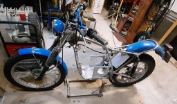
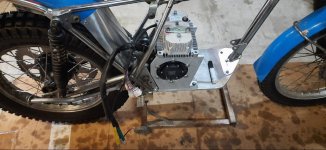
Meanwhile the motor is fixed, and has already spinned the rear wheel (with provisional wiring) :

6-MotorMounted5.jpg

I have been cursing quite a lot when building the brackets-can't understand why QS made those 6 threaded holes on each side so stupidly close to the corner...

Now I am looking for places for the rest of the components-battery probably upright in front, and controller above the motor (as in the picture above).
If I put the controller there, the wires of the motor are way too long.
This brings me to another question:
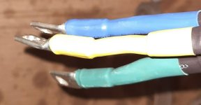
When having a closer look at those wires, I found that they are fat only at the end, where the eyelets for the controller are located.
Already a few Centimeters (~ one inch or so) from the end, the wires feel as if there were several loose thin wires inside the sheath, instead of one fat wire. I had thought I can just cut the fat wire and crimp on a new eyelet...

MotorCables.jpg

So my question:
Has anyone cut those factory motor wires? What do they look like inside the sheath ?
 
Depending on the motor "version" they can be more or less stranded and with different isolation material, but basically they are just copper wires.
Make sure to do a good crimping job with the new eyelets.
 
It feels like they're the winding's, just continued out as the cable rather than joined to a regular cable before leaving the motor. In the em100/150 thread there are some pictures from an unfortunate scooter fire with the same motor, fairly sure the bare cables are clearly visible in them (somewhere near the end of the thread iirc). As far as I know, shortening the cables is desirable and longer cables put more strain on the controller. Maybe worth shortening them after some testing, can't think of any reason you'd want to move the controller elsewhere, looks just right where it is but it's the sort of thing that always seems to catch me out :/
 
Back
Top