Elektrosherpa
1 kW
- Joined
- Feb 7, 2021
- Messages
- 386
Thanks for the info.
I guess I will just take the controller and go to an electric workshop and have the crimping done there,
rather than buying a 25/35/50 mm² crimping tool for 100 Euro, just to do 5 -10 crimps with it...
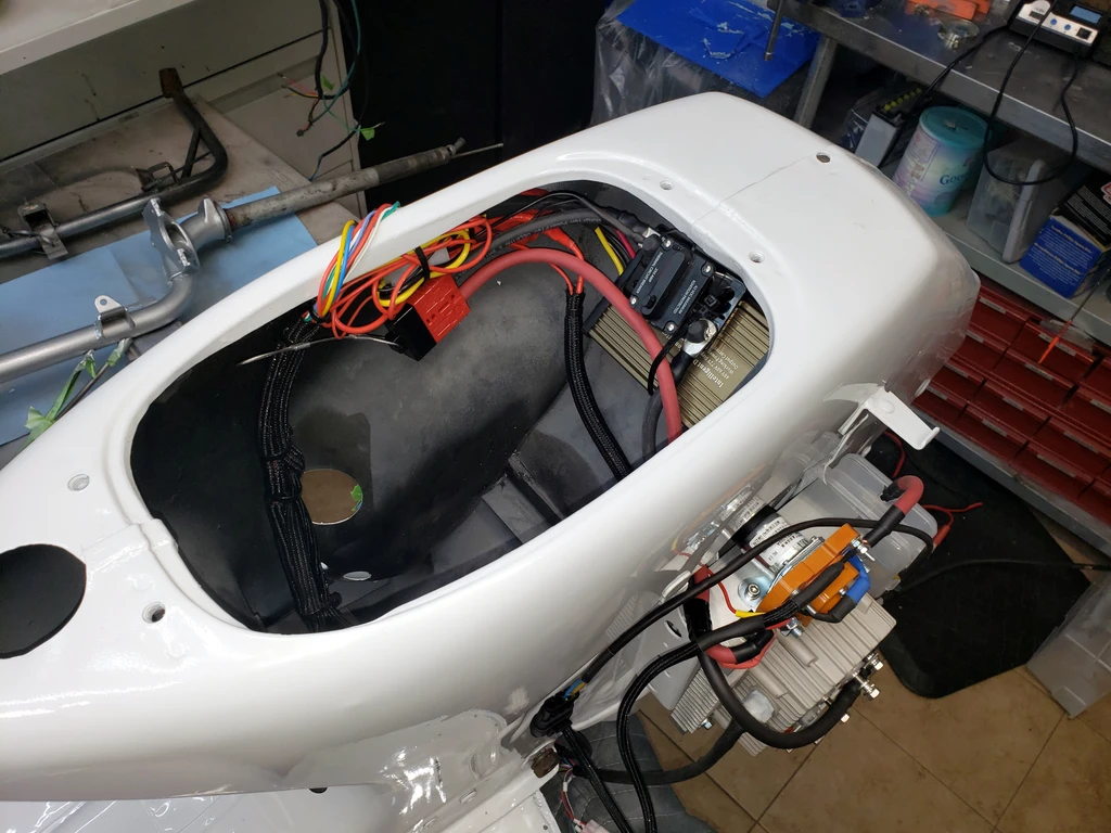
Meanwhile I have started planning the positioning of all the small components.
Another question arose from this:
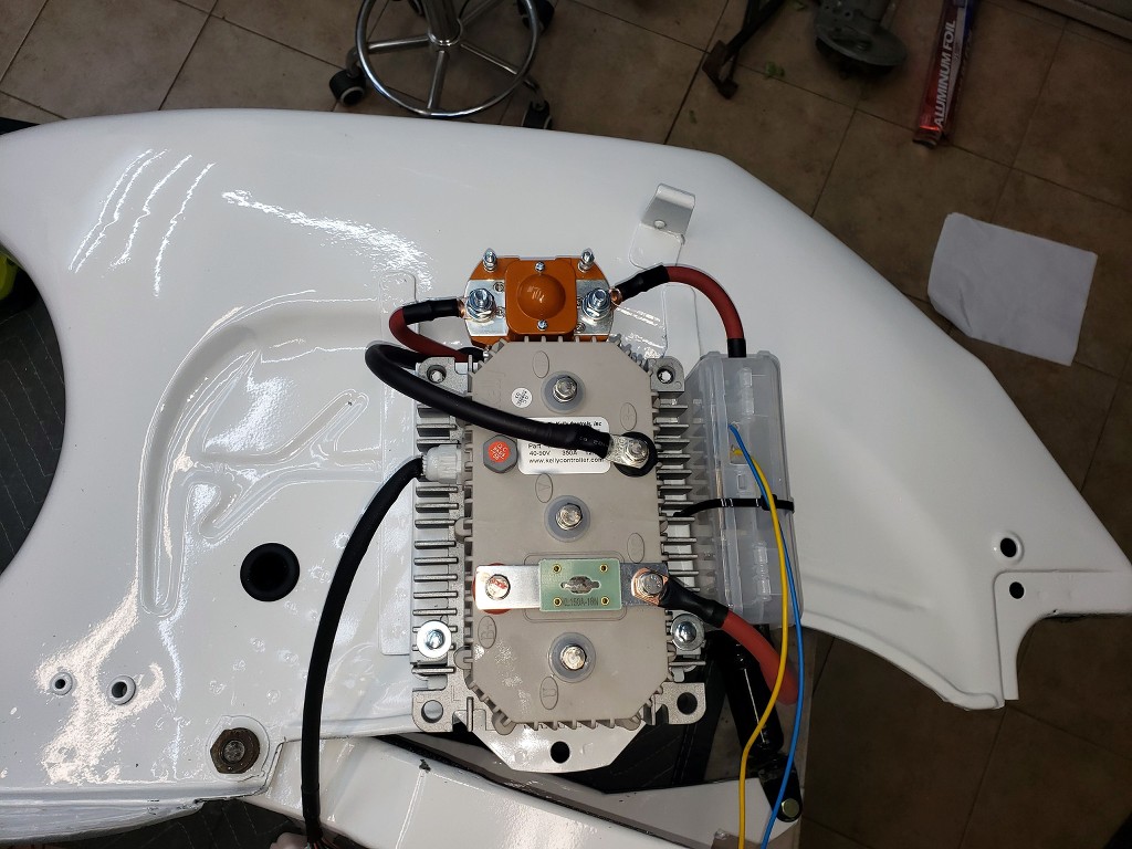
Most wiring plans include a ~200 A fuse somewhere- do I need one, too,
additional to the fat 150 A fuse on top of the Kelly controller?

AND 2nd:
As clearly visible in the picture above, the tag on the controller says "350A".
So why do they put a 150A fuse on it???
Here is a first "design idea" what the bike might look like in the end:

(I hope Senor Bultó 's spirit will not haunt me for changing the name "Bultaco" to "Eltaco" and "Sherpa T" to "Sherpa E" )
)
I guess I will just take the controller and go to an electric workshop and have the crimping done there,
rather than buying a 25/35/50 mm² crimping tool for 100 Euro, just to do 5 -10 crimps with it...
Meanwhile I have started planning the positioning of all the small components.
Another question arose from this:
Most wiring plans include a ~200 A fuse somewhere- do I need one, too,
additional to the fat 150 A fuse on top of the Kelly controller?
AND 2nd:
As clearly visible in the picture above, the tag on the controller says "350A".
So why do they put a 150A fuse on it???
Here is a first "design idea" what the bike might look like in the end:
(I hope Senor Bultó 's spirit will not haunt me for changing the name "Bultaco" to "Eltaco" and "Sherpa T" to "Sherpa E"