jateureka
10 kW
Some more Nexus / Sturmey Archery type fixed cog size options http://bikesmithdesign.com/cogs/index.html

Original bpm really can give 80 Nm, without damage the gears/windings.?crossbreak said:Jackshaft 98,72
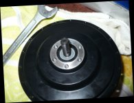
 I hate these, they always fail. If the Motor is not spoked into a rim it is impossible to open it :x stay away from these!
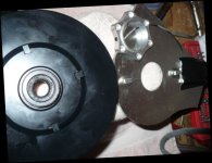
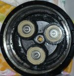
Gears (BPM2): Modul 1.25 14mm width Sun-gear: 21T Planets: 42T Ring-gear 104T Standard reduction 104/21 = 4.95:1
If sun and planets are the same, the ring gear must be: 2x planets+1x sun, so it's 105 for both :x So it is 5:1 exactly It sure looks like it. Also, on my BPM that you have apart, I think the spokes/side of the magnet bowl is also cast aluminum. Can you please verify that?spinningmagnets said:I know the magnet backing is steel, but...are the wide spokes of the magnet bowl face made from cast aluminum?
What is interesting is that the BPM II basket in this thread looks like the basket from an old BPM thread, and mine is different. Yet the BPM II has the screw-on sidecover, which I've thought was something on the newer motors, like the SWXK. Yet, I just got an SWXH and SWXU with bolted on sidecovers. I'm starting to think that Bafang have more than one production line that make different versions of the parts and they just assemble motors from what is on hand.

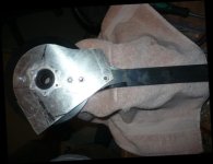
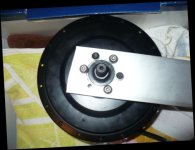
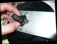
We grind down the center of the stator to make it run free without any friction on the shaft. This would not be possible with the motor you showed us. As you can see in the pics, the motor (rotor+stator) itself cannot run without an axle, since the stator is mounted on it. We mount the stator on the side plate instead of on the axle, using the "heat bridge" or thermal bridge that is screwed on the side cover. This way we can grind down th axle or the inner surface of the stator, so they dont rub against each other.However after implementing the conversion suggested by crossbreak, on this particular motor, wouldn't the axle at the stator-end (LHS of axle - in picture below) incur rubbing friction on the stator assembly?
nippynoo said:I've been following this very interesting topic and found the following diagram useful to help my understanding... which may help others. Its not a BPM, as you will observe that the axle is solid and the cable exits through the side, through the larger bearing, and it has a screw on cover. So could it be the Bafang SWXU or the QBPM or is it something else?
crossbreak said:The none-hollow-shaft motors, that dont use the axle as wire exit are not suitable for a conversion as you can see. The bearing design is not optimal. The bearing is too large, there is no radial space left for the screws that mount the stator on the hub housing / side plate. We grind down the center of the stator to make it run free without any friction on the shaft. This would not be possible with the motor you showed us. As you can see in the pics, the motor (rotor+stator) itself cannot run without an axle, since the stator is mounted on it. We mount the stator on the side plate instead of on the axle, using the "heat bridge" or thermal bridge that is screwed on the side cover. This way we can grind down th axle or the inner surface of the stator, so they dont rub against each other.
-dg said:Where did you find this diagram anyway?