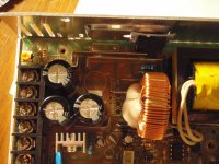
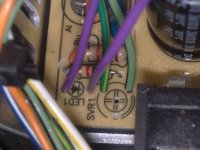
converting meanwell power suply into Lipo charger

Ok, got the charger, here are the pics. So the supplies already have a pot to adjust the voltage between the voltage range they are given? That actually makes a lot of sense...

So I need a current limiter instead of voltage if I'm charging some lipo's at 44v with it? I'm under the impression that if I hook it straight up to the battery, with voltage set to max pack voltage it will charge the lifepo4 correct?
 

Attachments

  • charger.jpg
    charger.jpg
    444.9 KB · Views: 2,838
  • charger 2.jpg
    charger 2.jpg
    432.5 KB · Views: 2,838
bandaro said:
So I need a current limiter instead of voltage

yes, need current limiting...and this board does not have the SVR2 current limit layout in teh top right hand corner...so cant help you with modding the board.

BUT

another way wouls be to use one of the Fechter meanwell current limiting boards

http://endless-sphere.com/forums/viewtopic.php?f=31&t=21768
 
R33 is on the board... I dont see r37 tho. but they both technically are the same thing. So there is hope in modding it.. this is just a different variant than what we are used to.
 
well if R33 is the same, then a 5 k pot across it will do the current limiting just fine
 
You will need to get the board out the case, and trace the tracks that come from the shunts J1 to J4 and compare them to the schematic Kingfish produced and created a link to earlier in this thread.

Find a resistor or resistor string that is connected to the chip (16 pin ...possibly TL494...) doing a similar job, to R22 R37 and SVR2 on the schematic, then fir a pot in a similar place on your board...mount it externally so you can have easy on the fly adjustment
 
I can shed some light on that meanwell clone pictured.

Its the exact same one i have. Top right corner of the first pic there are 3 resistors in parallel running vertically. middle one next to the black cilinder is R33.

remove the board from the case. (you will have to unscrew the transistors from the sides of the case) flip the board and unsolder that resistor. Using an ohm meter read the value across the transistor. In my case it was about 530 Ohm. Set your pot to a value slightly higher than that, say 570 Ohms and solder it in.

One other mod i suggest you do is to jumper the connections on the fan temp controller (for the love of me i cant remember what its called right now). If you want, when i get home i can take some pics, but right now i cant help any more in that department. This mod will have the fan running all the time and will get rid of the current spike that occurs when the fan turns on. With the fan running all the time u can adjust the current and not have it fluctuate with the fan cycling.

once u have it setup, attach a partially charged pack and use your amp meter to read the current draw. Fiddle with the pot until you get the desired amperage. Do note that amperage draw drops as the pack gets full so a partially charged pack might pull 7a/h but an empty one will pull more.
 
Red_Liner740 said:
remove the board from the case. (you will have to unscrew the transistors from the sides of the case) flip the board and unsolder that resistor. Using an ohm meter read the value across the transistor. In my case it was about 530 Ohm. Set your pot to a value slightly higher than that, say 570 Ohms and solder it in.

That maybe true of that particular model, I cant say for sure...but if you did that to R33 on an original Meanwell, that would INCREASE the current output not decrease it. To reduce the current limiting ( to give lower max current) , you need to reduce the value of R33 not increase it. That is why putting a pot across it works...As the value of the pot gets less, output current also decreases. So if you put a high value resistance pot across it (5k) the overall value of R33 remains almost the same, as you wind the pot down the combine parallel resistance gets less, and current reduces

Red_Liner740 said:
One other mod i suggest you do is to jumper the connections on the fan temp controller (for the love of me i cant remember what its called right now).

Thermistor?

The better mod than that is rather than mod the thermistor, find the transistor that controls the On/off of the fan. (Q5 in original Meanwell). Short out ( or put a switch across) the collector-emmitter. Switch closed fan on all the time, switch open, fan running fully auto.

This method is better because ( so I am told) it does not disable fan speed control, and you still keep the fan failure protection that will save the supply if fan fails.

With the fan always running you do not get the current change when fan kicks in, but having the switch means you can leave it on full auto (normal) if you do not want the fan running all the time
 
You very well might be right...i was under the impression that with no resistor in place the meanwell would self destruct in seconds.

As i blew that one up by trying to get rid of the "buzzing" noise and my current order of meanwells is backlogged cuz of the Canada Post strike i cant confirm yet. I will update when i get them modified.

As for the fan mod. I modified what was the easiest for me. Having a fan on all the time is easier than wiring in a switch. Same thing really, it all depends how u want to go with it.

NeilP said:
Red_Liner740 said:
remove the board from the case. (you will have to unscrew the transistors from the sides of the case) flip the board and unsolder that resistor. Using an ohm meter read the value across the transistor. In my case it was about 530 Ohm. Set your pot to a value slightly higher than that, say 570 Ohms and solder it in.

That maybe true of that particular model, I cant say for sure...but if you did that to R33 on an original Meanwell, that would INCREASE the current output not decrease it. To reduce the current limiting ( to give lower max current) , you need to reduce the value of R33 not increase it. That is why putting a pot across it works...As the value of the pot gets less, output current also decreases. So if you put a high value resistance pot across it (5k) the overall value of R33 remains almost the same, as you wind the pot down the combine parallel resistance gets less, and current reduces

Red_Liner740 said:
One other mod i suggest you do is to jumper the connections on the fan temp controller (for the love of me i cant remember what its called right now).

Thermistor?

The better mod than that is rather than mod the thermistor, find the transistor that controls the On/off of the fan. (Q5 in original Meanwell). Short out ( or put a switch across) the collector-emmitter. Switch closed fan on all the time, switch open, fan running fully auto.

This method is better because ( so I am told) it does not disable fan speed control, and you still keep the fan failure protection that will save the supply if fan fails.

With the fan always running you do not get the current change when fan kicks in, but having the switch means you can leave it on full auto (normal) if you do not want the fan running all the time
 
Red_Liner740 said:
You very well might be right...i was under the impression that with no resistor in place the meanwell would self destruct in seconds.

Likewise, you could be correct that it would self district in seconds with no resistor. Remember no resistor is the same as a exceedingly large resistor..., infinite resistance. Remember no resistor is infinite resistance between those two points, so max current output, no current limiting.
If the resistor was replaced with a link wire, that would likely produce no output.
 
Oh awesome, thanks a bundle for that, and for your help trying to back-engineer from the pics neil :p

So if I was to short out the thermistor or whatever it is, the fan would be on permanently? Sounds good to me, so what one is the thermistor thing? Still use a 5k pot to swap the resistor (r33) with, or another one?
 
I used a 2K pot as a 5K was not available in 10 turn and from what i metered across the resistor a 5K was not necessary.

That being said, that was on a 48V unit, other voltage units may have resistors that are higher value. I doubt it, as moving the pot by half a turn (changing the resistance from 530 to 570 ohm) netted a 1AMP draw difference.

NeilP, thank you so much for clearing that up. You are absolutely right and makes perfect sense.
 
bandaro said:
Oh awesome, thanks a bundle for that, and for your help trying to back-engineer from the pics neil :p

So if I was to short out the thermistor or whatever it is, the fan would be on permanently? Sounds good to me, so what one is the thermistor thing? Still use a 5k pot to swap the resistor (r33) with, or another one?

There are at least 3 different fan mods for an original Meanwell that I am aware of:
Thermistor
Transistor
One another..no idea what
Others???

I cant comment on what shorting the thermistor will do, it depends what the properties of the thermistor are..and how it is set up..so cant comment on that.

All I know about is the Meanwell transistor mod, that drives it on all the time, but leaves the speed control that the thermistor offers still in place.

Current limiting:
As Red says a 2k pot will do fine across the resistor.
Now this is all assuming that R33 on this design is the same as R33 on a Meanwell...if not, don't say I did not warnyou that this may not work...
So assuming it has the same function as in a Meanwell.

As you reduce the resistance of R33, the current reduces in proportion, so a 25% reduction in the R33 value will result in a 25% reduction in current.

First thing I would do is solder up a couple of leads from the top of the board either side of the resistor, out to your pot, 2k 5k 150k...does not matter at this point...just have it wound up to the highest value


Turn the power on to the supply and Connect up a discharged pack, with an ammeter in series. Monitor the current.


Edit Just had a thought...before you solder the wires either side of the R33...do what I say above and see what current you get out of the un modified supply. now once youknow what the unmodified supply gives out to a discharged pack...continue


Now start winding down the pot.

If R33 is the same as R33 on a proper Meanwell, then at some point the current should start reducing..and you may get some buzzing...thats a Switch mode PSU thing..do not like it but apparently does not harm...though I try to avoid it.

Now...what is the rated output of your supply 350Watt? and what voltage have you setup.....sorry I am typing this and not going to go back up the thread to find out...lazy bastard that I am...

SO;

P=IV
power= current * voltage

therefore

current = power/voltage

work out what current you need, bearing in mind your Supplies rated output power and the voltage you have set.

If you are not clear on putting two resistors in parallel...try google......you will no doubt find a better explanation than I will put here...on the wrong side of a bottle or two of nice red wine.

oh and this may help

http://www.sengpielaudio.com/calculator-paralresist.htm
 
Hey Guys, I've been trying to follow this thread and I am no electronics expert, but I want to start bulk charging 24s to 100volts. If I were to buy (2) meanwell PSP-600-48 and (2) meanwell current limiting boards from fetcher or auraslip, is that all I would need as far as parts? Thanks - Mark
 
And you can even get away without the current limiting board if you do the current limit mod ( R33) but search for that on the other threads...it has been done to death now

Or easier still get one of these that DoctorBass has been playing with

http://www.endless-sphere.com/forums/viewtopic.php?f=14&t=29096

http://www.bmsbattery.com/alloy-shell/28-alloy-shell-900w-lifepo4li-ionlead-acid-battery-ev-charger.html
 
Well, I have all the parts, (1) mini meanwell limiter board and wound up getting (2) "SP"-320-48's instead of "S"-320-48's. I have read every thread I can find and am unsure where to connect the voltage sense wire, and also if I need to do the R33 modification in addition to keep from going into 'hiccup mode' ? - Thanks
 
Voltage sense wire goes on to the top of the Meanwell board...behind the potentiometer on the front panel, LHS, yow will see a resistor. it goes on to one of the legs of that resistor...but i cant tell yo which one. You will have to trawl the threads to find the Pic ...look for a thread entitled Fetcher Mini meanwell limiter board...or similar
 
Well you are in luck...at least if they are the same as mine. i just had a look through my pics and there is a pic, that I took to show something else..bt you can just make out the orange wire I used to run to my limiter board

23032011038.jpg


I put my Meanwells in a case with an extra fan and switchable voltage and current limits. next stage will be to add some digital panel meters to show voltage and current on the front panel...if I can find the space for them and the three independent 12v supplies needed to run them

24032011052-crop.jpg

P4230506.jpg
 
Thanks Neil! I can't make out from the picture which resistor you attached it to. Looks like the R55. Did you remove the led & voltage adjuster?
 
Neil, you were talking about getting a 'stand alone CA' to monitor voltage & current. Good Idea, I think I'll do the same, I'll take it off my 'slow bike'. Thanks
 
Click on the pic and you will see a bigger version. You can just see the solder blob on the front resistor, LHS.

Yes removed the LED to the Meanwell case and the pot to the front panel. Actually fitted 8 pots, they look like a blue letter box in the picture. 4 pots for each supply.
2 connected to the Voltage pot and two connected to the Current limit pot (SVR2). They are switchable with the switch on Lower Left middl of the pic, just above the red banana plug that is the output. The other switch to the right, switches them between series and parallel
 
geetarboy said:
Neil, you were talking about getting a 'stand alone CA' to monitor voltage & current. Good Idea, I think I'll do the same, I'll take it off my 'slow bike'. Thanks
Never did it in the end...I forgot to ask Lyen to send me one when he sent my repaired controller back
 
Thanks again Neil, you are using the "S" model, not the "SP" model. I am still not sure if this is going to work, Kingfish added a "S" model into his series because of a problem with CC on the "SP". Doesn't the mini limiter board take care of that?
 
As you can see from my pics above, I cant easily get to mine to see what model I used..but i am fairly sure it will work the same. it may be worth you taking the PCB out of the case, and tracing the tracks to the resistor and comparing to the meanwell schematics, to confirm that it is still tying in to the same place on the board
 
Back
Top