Current Controller for RC ESCs

AussieJester said:
rhitee05 said:
Would it be useful to people to include a 5V supply in the box?
Prolly the only input of any value ill have for this thread it will be waaaaay above my head. But a big HELL YES for a 5v power supply, be very handy indeed if it was "all in one" unit ;)

You have no idea how i look forward to this working and becoming available for purchase lol

Best of luck with the project :)
Ditto my thoughts too. :D The only comment I'll add about the 5v supply is I know Matt is very picky about the quality of this part working with the servo throttle control for the ESC. I'm no electronics techie to help more, but I like your ideas you posted about this:
For the current limit, I'm thinking about a two-level design. The first would be fast-acting, designed to immediately pull the throttle to zero. The idea is this would prevent the sort of quick ESC exploding events you're all so fond of. The second limit would use a filter to act on the long-term average current, over a period of a second or more. This limit would be set to a lower level and be mostly aimed at keeping heating under control. I would also make this limit have a more progressive action, so it just throttles back instead of zeroing the throttle out. What do you all think of this approach? The limits would obviously be adjustable, and I might be able to provide some adjustment on the time scale of the average limit (at the least, adjustable by replacing a resistor).
Really excited to read about this, as this is a device we've needed for RC motor ESC setups since before fryday 1. :lol:

Hope you can find a working solution soon or at least inside of 2011. 8) :p
 
AussieJester said:
p.s i have recorded 280amp output with my HV160 dunno if thats of any help too you? I know Matt.S has done considerably more too.

Just to be clear, by "output" you're referring to current on one of the motor phase wires, correct? Not battery current. Is that a brief peak you've observed or a continuous value? Just trying to wrap my arms around the scale I should be expecting! I can scale it down for more, um, "reasonable" systems, but the design will be driven by the max value I need to accommodate.
 
rhitee05 said:
AussieJester said:
p.s i have recorded 280amp output with my HV160 dunno if thats of any help too you? I know Matt.S has done considerably more too.

Just to be clear, by "output" you're referring to current on one of the motor phase wires, correct? Not battery current. Is that a brief peak you've observed or a continuous value? Just trying to wrap my arms around the scale I should be expecting! I can scale it down for more, um, "reasonable" systems, but the design will be driven by the max value I need to accommodate.

Its the reading i have from the Caste Control data logging i gathered it was phase current but im always wrong, one of the guys will clear this up for you soz...

I agree this supply needs to be rock solid, one of mine blew 'on the bench' (bike was on stand) Hyena was hooking things up we heard a pop and the motor went from not on to full power...

KiM
 
Thanks for the feedback. Hopefully Matt and some other RC users can also weigh in. Seems like the Castle logger would likely display battery current, but hopefully someone can confirm. If that was battery current, it was something like a 14 kW peak! Either way, it seems likely that I'll need to allow for currents above 200A. I'm working on a couple of alternate options for this.

Reliability is something I need to pay careful attention to in the entire system. We all know to respect these powerful systems and a failure can't be allowed to create a dangerous situation. The final version will have to include some interlocks to prevent that.
 
Matt, do you have any numbers for the sort of current peaks you're seeing? I get the feeling that I'll need to accommodate >200A levels, at least for the instantaneous limits.

I'm working on a different sensor solution that should accommodate those levels. It will use linear Hall-effect sensors to sense the current indirectly without being in the conduction path. I've come up with a scheme that seems promising, but I'll need to test it. The trick will be to allow for ridiculous levels of current but still scale down to more pedestrian levels effectively.
 
So, here is the new concept for current sensing. The regular Allegro Hall-effect sensors only go as high as 200A, which doesn't look like it will provide enough range for high-power setups. There are ways to extend that by setting up a current divider with an external shunt, but that involves other complications. I'd like a simpler solution.

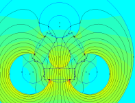
What I plan to do is to use the standard linear Hall-effect sensors to measure the current without being in the electrical path. These are similar to the sensors used in motors, but with a linear analog output instead of digital. I can use these to create a similar setup to the packaged current sensors, but with the range and scaling I need. Here's the configuration I've devised in my FEMM model:
Triple Hall Sensor.png

The three rectangles are the Hall sensors, which measure about 4 x 1.5 mm. The three smaller circles that form the corners of a triangle are the conductors. Here I've used wire with a similar diameter to 8 AWG. Surrounding the conductors and sensors is a steel ring which serves to concentrate and direct the flux. There's also a steel piece in the center of the sensors. This drawing shows it more clearly:

Triple Hall Sensor2.png

The configuration of the conductors and sensors is important. The flux is concentrated between the two active conductors with the help of the steel. Because the flux must loop back around, each of the other two sensors also see the flux, but of the opposite polarity and half the amplitude (ideally the sum of the three fluxes will sum to zero). With a little signal processing, I can combine the signal from all three sensors to get the final measurement. One really useful thing about combining the signals is that it'll reduce the noise and the tolerance of the individual sensors should average out somewhat for a more accurate measurement. It also lets the system operate in a sort of less-linear mode for really high currents. The sensor between the active conductors will saturate first, but the other two sensors will remain linear until twice the current, so the combined signal is still useable although it won't be quite as accurate.

My FEMM model of this configuration shows that the primary sensor will see about 4.4 G/A. The lower-sensitivity sensors are 2.5 mV/G with a usable range of +/- 2V. All of that works out to give me a fully-linear range of up to 180A and a "less-linear" range to 360A. If I need to go even higher, I can reduce the amount of steel slightly to lessen the flux coupling. For smaller units that don't need a super-high range, the sensors come in versions with 3.125 mV/G and 5.0 mV/G which would give linear ranges of 145A and 90A respectively. The averaging will hopefully make the signal useful at lower ranges, too.

I have some of the Hall sensors and an assortment of other parts on the way to do some testing. A 1" x 1/8" bar is just about the right size to make the flux ring out of, so I can pick one up at the local big-box store and gin up a quick-and-dirty prototype. I can work on the signal processing circuits to make this work in the meantime.
 
Current limiting on ESC controllers will be a dream becoming truth! Cant wait to get few of this. Still have 4 untoasted ESC controllers.

Question.
Ones after reprogramming (and getting very lame) Lyens 18 fet controller, he wrote me that “The formula to determine to phase current is: rated current x 2.6.” It worked on infineons.
Is it the same formula for ESC controllers? I have measured peak current of 190A on turnigy aquastar monster 240A. Is the phase current ~ 500A in this case?

P.S. Thank you for a great work!
 
parabellum said:
Ones after reprogramming (and getting very lame) Lyens 18 fet controller, he wrote me that “The formula to determine to phase current is: rated current x 2.6.” It worked on infineons. Is it the same formula for ESC controllers? I have measured peak current of 190A on turnigy aquastar monster 240A. Is the phase current ~ 500A in this case?

I think that formula is a rule of thumb for programming Infineons, but it's not applicable in general. I can't explain where it comes from.

In general, phase current is the battery current divided by the duty cycle. 190A battery current at 50% duty cycle would be 380A phase current, for example.
 
Ah, hi Eric, I have a question., which is "What does this do please?". I know it's a current limiter, but is it one that works fast enough to prevent a per-pulse (microseconds?) current exceeding the specs for the driver FETs inside the ESC? Is that what it's for?

Sorry for being dense, but I seem to think there are different sorts of current limiters somehow.

Cheers,

Eric
 
Erogo said:
Ah, hi Eric, I have a question., which is "What does this do please?". I know it's a current limiter, but is it one that works fast enough to prevent a per-pulse (microseconds?) current exceeding the specs for the driver FETs inside the ESC? Is that what it's for?

Not a silly question. In this application, the limiting factor for speed is the interface to the ESC. The standard servo interface sends pulses at a 50 Hz rate, which implies that the worst-case response time would be 20 ms. I'm hoping that the ESCs will accept a faster pulse rate, but 200 or 250 Hz is still about the best we could hope for, 4-5 ms. So, definitely not pulse-by-pulse limiting. That's still pretty fast, but not fast enough to protect the ESC from a really radical spike.

The Hall sensors I'm using have a bandwidth of about 20 kHz, so in theory they're more or less capable of doing pulse-by-pulse limiting if linked directly to the controller.
 
rhitee05 said:
In general, phase current is the battery current divided by the duty cycle. 190A battery current at 50% duty cycle would be 380A phase current, for example.

So, theoretically, if we go to 100% controller power, duty cycle will be about 100% and battery current will be about = to phase current. Is it right?
 
parabellum said:
So, theoretically, if we go to 100% controller power, duty cycle will be about 100% and battery current will be about = to phase current. Is it right?

Yes, exactly right. This is why low throttle/high load situations are so dangerous to controllers, because the duty cycle is low so the multiplication factor is high.
 
Little bit of a progress report. I got my box of toys today, including some Hall sensors. I need to pick up some steel bar and do a little drilling, then I can put together a test of my sensor concept. Testing with significant current levels is going to be a problem, I think. I can start with some benchtop supplies, but those will only do a handful of amps. I'll have to prowl around the labs on campus and see if I can rig something better. I have 10 Ah of 20C LiPo, so I might have to build myself a little PWM-controller FET rig to make use of that. We'll see. To start with, I'll be happy so long as I can get enough current flow to check the coupling and sensitivity against my FEMM model.

Finished the design for the signal processing circuitry, after several revisions. I made a design decision to split the circuit into multiple boards. The signal processing circuit will be on one board along with the Hall sensor module. The "brains" (in this case strictly analog) will live on a second board stacked directly below. I like this for two reasons. First, I can develop the sensor/processing module separately. When I'm happy with it, I can leave it alone while I develop incremental versions of the control module. Second, I have some ideas that there may be benefit from stacking a 2nd sensor module and using a total of 6 Halls - this configuration makes it easy to try.

Here's a shot of the draft board layout:
Sensor Board.png

It's just a draft at this point until I test the sensor and breadboard the circuit, but I finished the layout to prove my packaging concept. The dimensions of this board are 1.4" x 2.25". The board stack should be less than 1" tall.
 
rhitee05 said:
It's just a draft at this point until I test the sensor and breadboard the circuit, but I finished the layout to prove my packaging concept. The dimensions of this board are 1.4" x 2.25". The board stack should be less than 1" tall.
Great progress Eric! :D

Most Excellent to have everything fit into this small sized packaging. I hope you have the time & energy to see this project through to completion, since this looks so promising & you've got the ability to do it too. 8)
 
Thanks, deVries.

One of my goals is definitely to try and make this a nice, small package. I'm sure I can probably make it smaller still if I put more effort in. Also, even those I'm already using surface-mount parts I chose relatively large packages for this iteration, so I could down-size there as well. SMT makes the assembly a little more challenging but its worth it.

A big packaging issue I'll need to figure out is how the phase wires will connect in. The currents are so high I'd have to use ridiculously large connectors. Anyone have suggestions? How do most of you end up connecting the ESC to the motor - do you use connectors, or do you just solder it and forget it?
 
I always use this connectors. Male on controller side and female on motors.

http://www.hobbyking.com/hobbyking/store/uh_viewItem.asp?idProduct=12887

rhitee05 said:
A big packaging issue I'll need to figure out is how the phase wires will connect in. The currents are so high I'd have to use ridiculously large connectors. Anyone have suggestions? How do most of you end up connecting the ESC to the motor - do you use connectors, or do you just solder it and forget it?
 
Finally some useful progress to report. My hall sensors arrived and I built a very quick-and-dirty proof of concept for the sensor. Bottom line - it works! Really good measurements were limited because I was using a benchtop supply which could only give me 5A, but this showed a sensitivity of about 20 mV/A. My FEMM simulation of this configuration showed a coupling of 4.8 G/A, coupled with the 5 mV/G sensors, so the theoretical sensitivity was 24 mV/A. That's 20% off, but I consider that very good considering the crude assembly. I would never expect a real-world device to quite match the simulation anyway.

TriHall_Proto2.JPG

Apologies for the bad photo quality, these are taken with my phone. Fortunately for me, the bad photos partially obscure the very bad workmanship. :) I had some issues with a balky PCB mill and trouble finding tools in the small, poorly-equipped and badly neglected machine shop I have access to. Here's the FEMM sim, which shows the structure better:


The hall sensors are in the center, with the conductors at their outer edges. The outer ring is 1/2" EMT thin-wall electrical conduit, with 3 pieces of 1/4" steel rod in between the sensors. In the prototype, I cut each of those to about 1/4" lengths and used a little hot glue to hold everything in place. This construction makes the assembly a little more difficult, but I was mostly driven by my limited ability to machine anything. I was able to build this with nothing fancier than a Dremel. For scale, the outer dimensions of the little PCB above are roughly 1.15"x1.3".

I need to get the manufacturing issues figured out going forward - this configuration is too labor-intensive to work in any quantity. The previous configuration I posted would work better, if I can find a place to machine some pieces of steel plate inexpensively. I'm also going to do some breadboarding of the circuitry, as well. Compared to the mechanical, the electrical is easy! :)
 
looks promising, excellent job thinking outside of the box.

I myself and most other people running hv160s can all say they see at least peaks of 160amp battery current. Without the current limiting turned on you see peaks up around the 200A mark, or more in Matts yellow trikes case. What that relates to in phase amps is anyones guess. Could the error(20%) in your test results be the result of the sensors spaced further than optimal away from the conductor. Im not exactly sure how it works (e-douche) but I'm gathering you are sensing the magnetic field around the conductor. If thats the case maybe you dont have to source sensors above 200A. Just space them futher away from the conductors.....make a low current and high current version i suppose. Maybe I am missing how it works :oops: .

If you get it figured I will have my name down for one or ten :wink: . Im not sure if it has been mentioned before but it would be handy if it accepted a hall or 5k throttle and turned the signal into what the esc understands.....kind of a all in 1 unit.

Cheers

edit: looks like I need to do less night shifts and more reading and comprehension :oops:. The hard cutoff (zero throttle ) sounds like a very good idea, problem is no body knows the point that their controllers flame up especially in phase amps. How are you going to make it adjustable? :wink:
 
rodgah said:
. Im not sure if it has been mentioned before but it would be handy if it accepted a hall or 5k throttle and turned the signal into what the esc understands.....kind of a all in 1 unit.
rhitee05 said:
And since I'm already doing the throttle and this is intended for an ESC, I figured I might as well include the servo tester function as well. The result will be a box which takes the throttle input, measures phase current, and commands the ESC accordingly.
 
rodgah said:
Could the error(20%) in your test results be the result of the sensors spaced further than optimal away from the conductor. Im not exactly sure how it works (e-douche) but I'm gathering you are sensing the magnetic field around the conductor. If thats the case maybe you dont have to source sensors above 200A. Just space them futher away from the conductors.....make a low current and high current version i suppose. Maybe I am missing how it works :oops: .

You're not very far off in how it works, but the steel components make it a little bit counter-intuitive. What you said would be entirely correct if I put a sensor next to the wire in free space (no iron/steel nearby). The field would reduce quite rapidly (1/r) as the distance increases. However, having a ring of ferrous material around the wire almost completely eliminates the effect of distance. The sensor will measure almost the same field so long as the wire passes through the ring, no matter where.

I get some adjustability from the hall sensors, because they come in a few different ranges. After that, the way to adjust the sensitivity for low and high currents is to adjust the width of the air gap where the sensor is located. Larger gap, lower sensitivity.
 
Parra,
This particular unit is addressing sensorless controllers specificly. Many of the high end sensorless controllers are on the cutting edge regarding the timing curves for power output. But they are subject to increadble strain from hot wound motors being used to drive a bicycle.

Burties lovely timing device is a hall sensor interface that will ellectronicly synthisize the positions of the halls effecting timing in sensord controllers. (something the sensored controllers are lacking)

Although this is a better way (true phase current measuring) to controll the energy allowed thru a controllers more sensitive bits.
 
Thud said:
Parra,
This particular unit is addressing sensorless controllers specificly. Many of the high end sensorless controllers are on the cutting edge regarding the timing curves for power output. But they are subject to increadble strain from hot wound motors being used to drive a bicycle.

Burties lovely timing device is a hall sensor interface that will ellectronicly synthisize the positions of the halls effecting timing in sensord controllers. (something the sensored controllers are lacking)

Although this is a better way (true phase current measuring) to controll the energy allowed thru a controllers more sensitive bits.

Sorry Thud and rhitee05.
Removing and editing my original post to avoid misunderstanding (it was for other tread)
 
Back
Top