Current Controller for RC ESCs

nieles said:
eric, how hard would it be to also have the option to use a "rc 20ms signal" for the throttle input? this could be handy for mountainboards and rc cars.
maybe add this option on its own pcb and add it to the stack if you want this option.

You mean have the board accept the PWM RC-type throttle signal as an input instead of the analog throttle? Probably not too difficult, although I'd have to think about the exact circuit. It should be possible to make a simple circuit that could sit as an add-on 4th board.
 
yes thats what i mean.

i found something that could work.

http://homepages.which.net/~paul.hills/Circuits/RxDecoder/RxDecoder.html

but the signal needs to be 1.5-2ms for 0-100%
 
Yes, something along those lines should work well. I would probably make a few small tweaks to his circuit, but it's basically what's required.
 
sorry for the lack of updates on this project.

next week i will be off from work, so i will have more time to work on this.
i have an CC ICE160A controller on order, so hopefully it will arrive in time to do some testing.

thud, do you have an setup ready for testing? if so, i will send you my working device and build a new one for my self.
i do not have enough parts to make many more test units, so the rest of the people have to wait a little longer.
(i only need to check if it will survive a extended period on 50v)

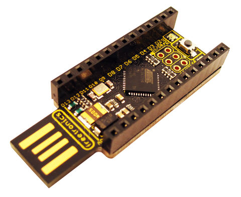
eric, i was thinking it would be cool if we add a arduino board to the stack, this could be used for all kind of stuff.
i have a mini pro board on order to experiment with. this could be used as a rc decoder, instead of a analog circuit.

Niels
 
Yes, an arduino could definitely be used. Depending on what you wanted to do, an Arduino could completely replace the entire throttle board, as all that could be done in software. The original design concept was to build something that would implement the basic functions in hardware without a processor. You could replace all of that functionality and more using any MCU and software.
 
This is one of the most important addons to put on a ebike!!!!

Any news, other topics???

Working stuff???
 
looks like this thread is dead...

anyway i think an arduino or other programable ic would be just about all you need. maby some solid state relays and optical isolators.
http://www.freetronics.com/products/leostick#.UV9hhDf_6vU
IMG_3380_b_LS_headers_top_angle_large.png

$29 good price. they have a good relay board i have used to, its just 4 fets basicaly npn transistors with smd leds.
 
The CA does not do what this project does.

CA only measures and regulates current battery side, this measures current motor side of the controller.

Very different scenarios.

Personally, i would love to see this project completed, it would make using much cheaper escs and not killing them available to the masses...

D
 
Danny Mayes said:
The CA does not do what this project does.

CA only measures and regulates current battery side, this measures current motor side of the controller.

Very different scenarios.

Personally, i would love to see this project completed, it would make using much cheaper escs and not killing them available to the masses...

D
interesting, how do they differ? more accurate?
 
I'm no expert on this. Maybe one of the controller guys can chime in.

Luke has explained a number of times the dangers of trying to control the current on the battery side. The current on the motor side of the controller can be many, many times what it is on the battery side and this is what needs to be monitored and limited...

This is what this project set out to do. The CA only measures battery current, not phase current. Does that make sense?

I could have this completely wrong but i think i am in the ball park. Hopefully someone who is trained in this can confirm.

It is well documented in the many threads on controllers.

D
 
sorry for the lack of updates on this thread.
2 big obstacles, time (very busy with school, first year EE) and the lack of a good test platform

when i get around to it, i would like to build an inertia dyno to do the testing.
the last time i worked on the current controller, it just stopped working for no reason. so the next time i will build the controller in phases, and test each part individually, then move on to the dyno testing, and tuning of all the control loops.


Danny Mayes said:
I'm no expert on this. Maybe one of the controller guys can chime in.

Luke has explained a number of times the dangers of trying to control the current on the battery side. The current on the motor side of the controller can be many, many times what it is on the battery side and this is what needs to be monitored and limited...

This is what this project set out to do. The CA only measures battery current, not phase current. Does that make sense?

I could have this completely wrong but i think i am in the ball park. Hopefully someone who is trained in this can confirm.

It is well documented in the many threads on controllers.

D

yes factor between phase and battery current is mainly dependent of the duty-cycle. (and a few more, but duty cycle is the biggest one)
 
Back
Top