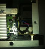
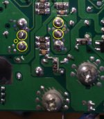
heathyoung
100 kW
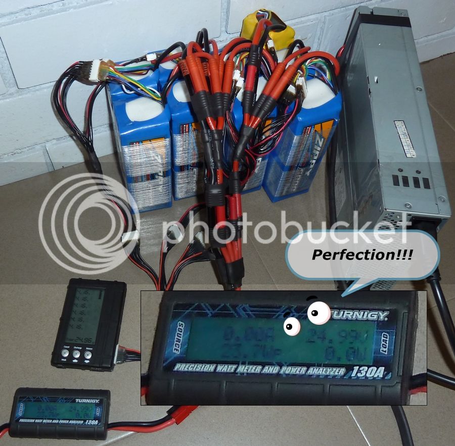
TL R - circuit allows high current server power supplies to be used directly as bulk chargers, by adjusting their output voltages all together to current limit. Allows multi-kw charging really, really cheaply.
OK - I have a large collection of HP power supplies, removed from decomissioned servers from work.
While they work great for powering LiPo chargers, they really aren't suitable for bulk chargers - put them on too big a pack and they just shut down. Sigh.
I considered making big, expensive, high-current buck converters, but the thought of designing a 50A buck didn't really appeal - big bulky, and expensive. :?
While messing with a HP DPS-600PB, I discovered that it has an adjustment range of 8-13.5V reliably. Great, but what's the use of only having one adjustable? People have been having issues with killing meanwells because they only adjust one while bulk charging. 8-13.5V is a great range when charging 3S, but I want to charge more than 3S.
So what to do? Adjust all of them together, from one point. How? Isolate them. How? Optos.
HP DPS-600's have a voltage adjustment pin - Pin 9.
Here is a pinout swiped from an RC site
PIN ------------ Ribbon Wire
1----------------- +5VSB, not on ribbon wire
2----------------- +5VSB, not on ribbon wire
3----------------- +5VSB, not on ribbon wire
4----------------- 3 (Controls fan speed)
5----------------- -12V, not on ribbon wire
6----------------- 5 (PsKill)
7----------------- 6 (not sure what this one does)
8----------------- Ground, not on ribbon wire
9----------------- 8 (Voltage Adjust)
10---------------- 4 (PsOn)
11---------------- 9 (Current Share)
12---------------- 7 (not sure what this one does)
Shorting 6-8-10 turns the PS ON.
Shorting 4-8 slows fan speed to minimum.
Putting a variable resistor between 3-9 allows voltage adjustment up to 13.8V (5V)
Putting variable resistor between 5-9 allows voltage adjustment down to 8V (-12V) - OCP is 30A at 8V though.
Now, the juicy stuff - Circuit Notes
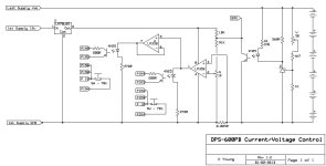
There are two elements to this circuit.
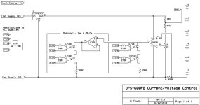
Voltage Control (more on this later) and current control. Current control is achieved through the use of a LM358 as a comparator, powered
through a low dropout 5V regulator running on the '12V rail' (which is adjustable between 8-13.5, and is the reference voltage for the comparator).
When the current limit is exceeded, the output of the comparator (pin 1) goes high, and the optocoupler starts to conduct, pulling the voltage control pin (pin 9 on the PSU) down using the -12V rail (pin 5 on the psu). This causes the power supply to reduce in voltage so that the current limit is not exceeded.
The second opamp is simply a voltage follower, and causes the second optocoupler to do exactly the same thing.
One opamp is capable of driving 40mA, each optocupler consumes 15mA - so the two opamps can drive 4 optocuplers between them - enough for 4 power supples, or if the current is dropped to the optocoupler LED's by increasing their series resistors, they could drive 6.
The voltage control works by using a TL431A precision zener, when the voltage reaches its set point, it forces another optocoupler to pull the shunt reference resistor to ground, forcing the comparator to go high, and switch on the optos and pull down the voltage on all of the supples. The 'BMS' point serves exactly the same purpose, and does exactly the same thing when it is pulled low by an optocoupler transistor.
The voltage control section is neccesary only if the voltage of the power supply is too high for your application. But is probably a good idea in case something happens and a PS drifts high.
The component values shown at the moment are experimental ONLY - this design will be revised as it is being tested and built.
There are a few component values that will require changing - the shunt resistors ie. the 5K trimpot, the 4K7 resistor, the 560R resistor, the 1K8 resistor - for 48V, double these values.
The normally closed 70 degree thermostat on the fan control pin is not absolutely neccesary, but does provide a degree of protection against overheating. It can be omitted, and pin 4 can be wired directly to pin 6/8/10. This ensures the fan goes flat out when the temperature exceeds 70 degrees celcius.
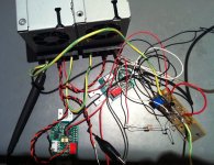
I'll probably do some more testing this weekend, and come up with a nice simple PCB as well that will fit inside a power supply if possible.
OK - I have a large collection of HP power supplies, removed from decomissioned servers from work.
While they work great for powering LiPo chargers, they really aren't suitable for bulk chargers - put them on too big a pack and they just shut down. Sigh.
I considered making big, expensive, high-current buck converters, but the thought of designing a 50A buck didn't really appeal - big bulky, and expensive. :?
While messing with a HP DPS-600PB, I discovered that it has an adjustment range of 8-13.5V reliably. Great, but what's the use of only having one adjustable? People have been having issues with killing meanwells because they only adjust one while bulk charging. 8-13.5V is a great range when charging 3S, but I want to charge more than 3S.
So what to do? Adjust all of them together, from one point. How? Isolate them. How? Optos.
HP DPS-600's have a voltage adjustment pin - Pin 9.
Here is a pinout swiped from an RC site
PIN ------------ Ribbon Wire
1----------------- +5VSB, not on ribbon wire
2----------------- +5VSB, not on ribbon wire
3----------------- +5VSB, not on ribbon wire
4----------------- 3 (Controls fan speed)
5----------------- -12V, not on ribbon wire
6----------------- 5 (PsKill)
7----------------- 6 (not sure what this one does)
8----------------- Ground, not on ribbon wire
9----------------- 8 (Voltage Adjust)
10---------------- 4 (PsOn)
11---------------- 9 (Current Share)
12---------------- 7 (not sure what this one does)
Shorting 6-8-10 turns the PS ON.
Shorting 4-8 slows fan speed to minimum.
Putting a variable resistor between 3-9 allows voltage adjustment up to 13.8V (5V)
Putting variable resistor between 5-9 allows voltage adjustment down to 8V (-12V) - OCP is 30A at 8V though.
Now, the juicy stuff - Circuit Notes
There are two elements to this circuit.
Voltage Control (more on this later) and current control. Current control is achieved through the use of a LM358 as a comparator, powered
through a low dropout 5V regulator running on the '12V rail' (which is adjustable between 8-13.5, and is the reference voltage for the comparator).
When the current limit is exceeded, the output of the comparator (pin 1) goes high, and the optocoupler starts to conduct, pulling the voltage control pin (pin 9 on the PSU) down using the -12V rail (pin 5 on the psu). This causes the power supply to reduce in voltage so that the current limit is not exceeded.
The second opamp is simply a voltage follower, and causes the second optocoupler to do exactly the same thing.
One opamp is capable of driving 40mA, each optocupler consumes 15mA - so the two opamps can drive 4 optocuplers between them - enough for 4 power supples, or if the current is dropped to the optocoupler LED's by increasing their series resistors, they could drive 6.
The voltage control works by using a TL431A precision zener, when the voltage reaches its set point, it forces another optocoupler to pull the shunt reference resistor to ground, forcing the comparator to go high, and switch on the optos and pull down the voltage on all of the supples. The 'BMS' point serves exactly the same purpose, and does exactly the same thing when it is pulled low by an optocoupler transistor.
The voltage control section is neccesary only if the voltage of the power supply is too high for your application. But is probably a good idea in case something happens and a PS drifts high.
The component values shown at the moment are experimental ONLY - this design will be revised as it is being tested and built.
There are a few component values that will require changing - the shunt resistors ie. the 5K trimpot, the 4K7 resistor, the 560R resistor, the 1K8 resistor - for 48V, double these values.
The normally closed 70 degree thermostat on the fan control pin is not absolutely neccesary, but does provide a degree of protection against overheating. It can be omitted, and pin 4 can be wired directly to pin 6/8/10. This ensures the fan goes flat out when the temperature exceeds 70 degrees celcius.

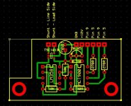
I'll probably do some more testing this weekend, and come up with a nice simple PCB as well that will fit inside a power supply if possible.


