
You are using an out of date browser. It may not display this or other websites correctly.
You should upgrade or use an alternative browser.
You should upgrade or use an alternative browser.
Custom frame for the Cyclone Coaxial motor
- Thread starter Chambers
- Start date
Tommm said:Chambers said:coaxial -27.JPG
Thinking about inserting the battery from underneath - through the motor mount. This would keep the frame much stronger than having a large cut out.
Could still have an 'inspection window' but it wouldn't need to be as large.
This would also mean I could make the down-tube even smaller because I wouldn't need flanges for bolting the door/panel.
Could save +/- 20mm in the vertical direction on the taller frame - The other one already inserts from the bottom but is offset from the motor mount.
How does it go *through* the motor mount?
Through a cutout in the mount - I figure I can make the mount out of 3 or 4 mm steel which would be plenty strong enough.
Or the motor mount could be two separate pieces that bolt together.
Still have to wait till I have the motor in my hands though.... I'll probably have a different idea by then :lol:
Coaxial frame has it from 2.3mm steel as painted
Motor is 5.5kg without cranks or pedals 136mm diameter.
I finally got QS motor to measure their 2000w mid motor, it is 142.5mm. So if you want it interchangable, go bigger and clamp it smaller rather than going for a perfect fit.
Motor is 5.5kg without cranks or pedals 136mm diameter.
I finally got QS motor to measure their 2000w mid motor, it is 142.5mm. So if you want it interchangable, go bigger and clamp it smaller rather than going for a perfect fit.
If you use the QS motor which is indeed a good and solid Motor you only use the throttle without pedaling. So a slightly different driving experience, more like motorbike style, right?Tommm said:Coaxial frame has it from 2.3mm steel as painted
Motor is 5.5kg without cranks or pedals 136mm diameter.
I finally got QS motor to measure their 2000w mid motor, it is 142.5mm. So if you want it interchangable, go bigger and clamp it smaller rather than going for a perfect fit.
Elaguila said:If you use the QS motor which is indeed a good and solid Motor you only use the throttle without pedaling. So a slightly different driving experience, more like motorbike style, right?Tommm said:Coaxial frame has it from 2.3mm steel as painted
Motor is 5.5kg without cranks or pedals 136mm diameter.
I finally got QS motor to measure their 2000w mid motor, it is 142.5mm. So if you want it interchangable, go bigger and clamp it smaller rather than going for a perfect fit.
Correct, it would be a bit more quiet and trouble free as there is no internal clutch, internal reduction or external pedal clutch.
You would still retain a freewheel on your hub so your range wouldn't suffer from the motor always being engaged.
https://m.aliexpress.com/item/4000076478471.html
As far as the motor part goes it is a bit beefier, but I am 80a 72v battery limited anyway and that's not changing in a hurry.
I figured out how to mount foot pegs on the motor mount in a way you aren't putting extra stress on the motor bolts.
You could use universal foot pegs and an alu long cnc bar squar piece with 3 holes where the motor clamping bolts go. Just need an extra long set of bolts.
I am also thinking of a devilish way to put some square taper cranks onto the foot peg stubs just for show, so I could continue to sneak it up some trains if I have to. :lol:
Tommm said:Elaguila said:If you use the QS motor which is indeed a good and solid Motor you only use the throttle without pedaling. So a slightly different driving experience, more like motorbike style, right?Tommm said:Coaxial frame has it from 2.3mm steel as painted
Motor is 5.5kg without cranks or pedals 136mm diameter.
I finally got QS motor to measure their 2000w mid motor, it is 142.5mm. So if you want it interchangable, go bigger and clamp it smaller rather than going for a perfect fit.
Correct, it would be a bit more quiet and trouble free as there is no internal clutch, internal reduction or external pedal clutch.
You would still retain a freewheel on your hub so your range wouldn't suffer from the motor always being engaged.
https://m.aliexpress.com/item/4000076478471.html
As far as the motor part goes it is a bit beefier, but I am 80a 72v battery limited anyway and that's not changing in a hurry.
I figured out how to mount foot pegs on the motor mount in a way you aren't putting extra stress on the motor bolts.
You could use universal foot pegs and an alu long cnc bar squar piece with 3 holes where the motor clamping bolts go. Just need an extra long set of bolts.
I am also thinking of a devilish way to put some square taper cranks onto the foot peg stubs just for show, so I could continue to sneak it up some trains if I have to. :lol:
Personally if I were to use the QS2000 I would design a specific frame for it allowing for pedals. Some of my earlier designs were based around the QS138-70h, The problem is the QS motors are really wide. If someone wanted to do this with one of my frames (If they get to production stage) they could potentially mount a bottom bracket just in front of the motor mount.

I have my old cranks and a spare coaxial axle
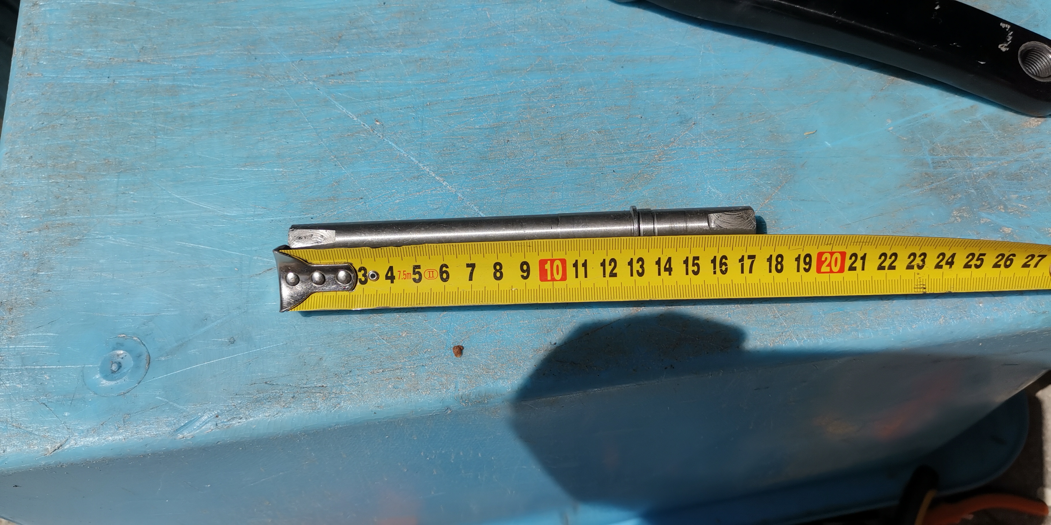
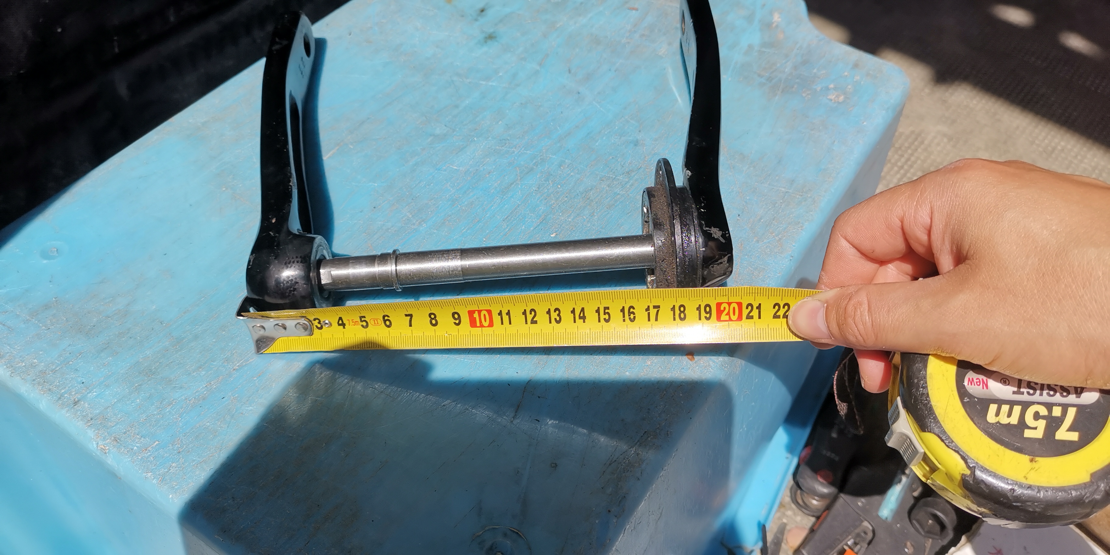
If you measure axle to axle coax is 175 and qs 211. If you measure crank head to crank head, coax is right about 200mm.
I strongly recommend a smaller trials crank I got jitsie jie 140mm. This will make your axle less likely to bend in a crash with a heavy bike. I bent my first one so bad that it seized. The taper and freewheel quality wasn't great either, my freewheel locked up on the first ride. I have a dnp freewheel (called gen1 freewheel) coming from cyc, but you can get one from sickbikeparts too.
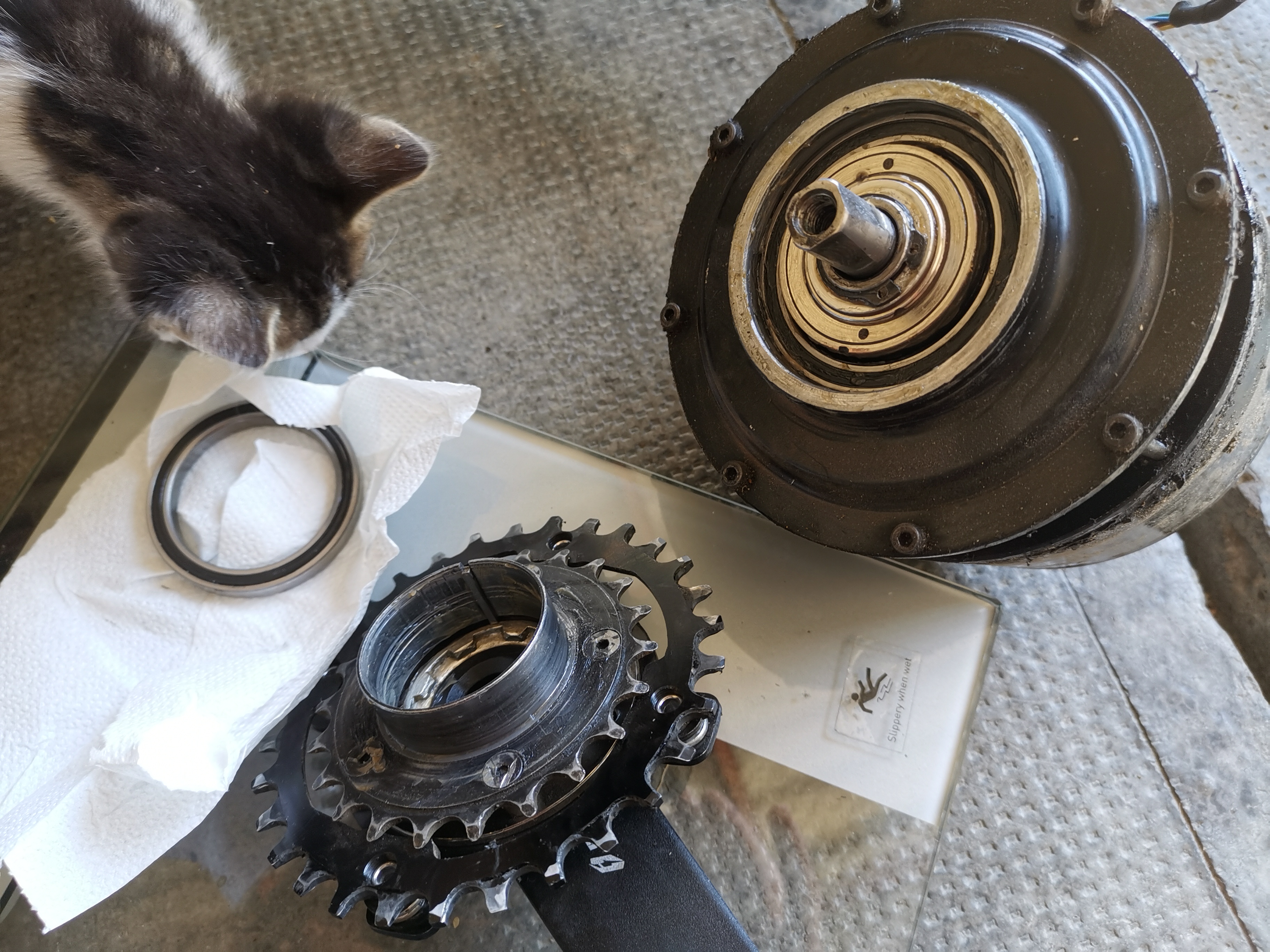
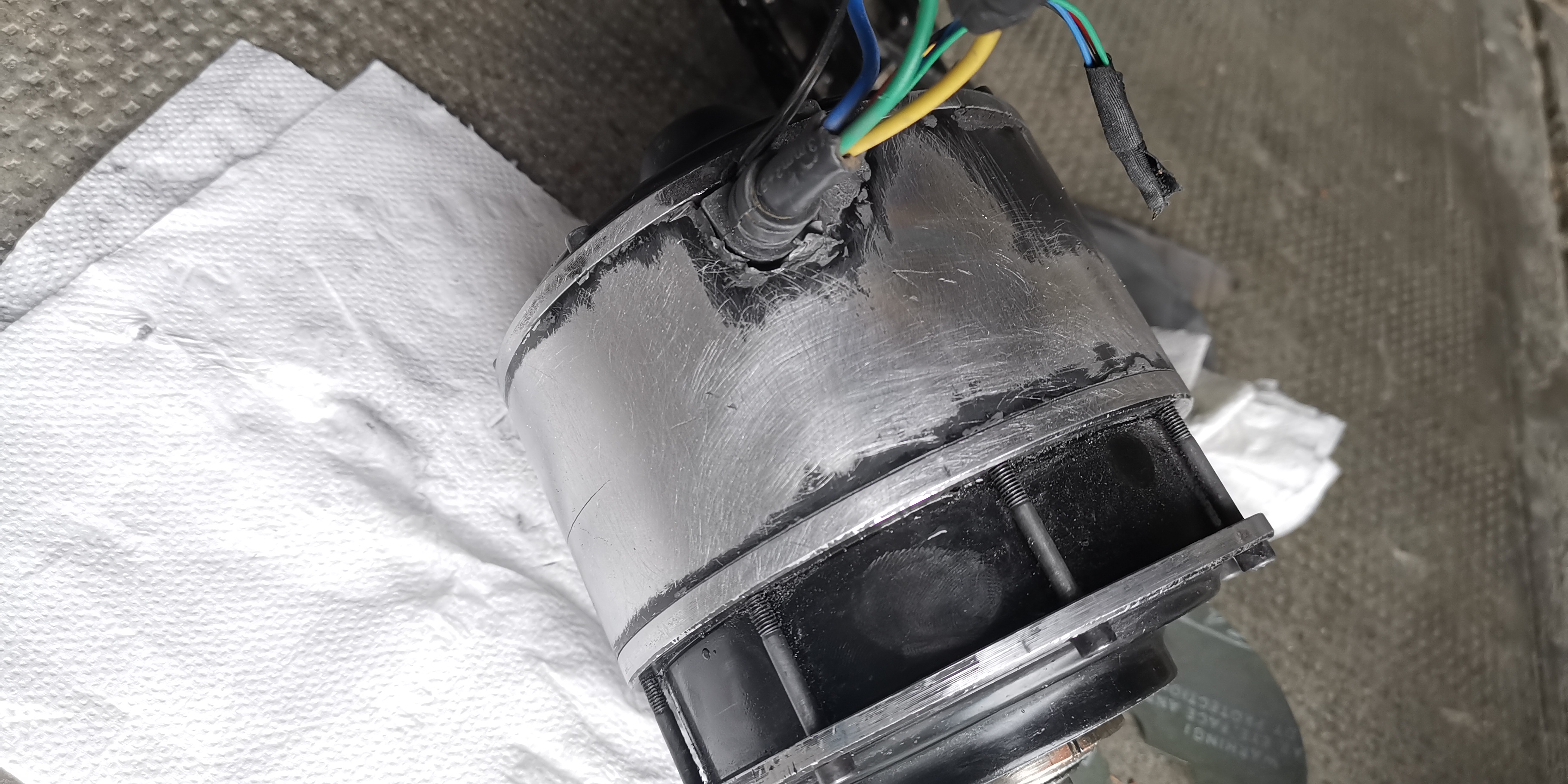
The sprocket carrier from the motor is welded to the default 22t sprocket, (which you can and should ignore) is a consumable part on this motor, along with the 2x2mm square metal rod that couples them together(replacable on ebay for ~$3), along with the axle if you are planning on letting the bike hit it's side crashing off road. They are all made of mild steel and will roll up over time, without any serious abuse. Cyclone sells the sprocket carrier for $50+ship(same as the machined axle) which isn't great, but understandable for a low quantity welded part. I just wish it was a harder material. The design doesn't allow for a thicker part between the bearing and clutch.
I won't mention the other repairs (about half of them my fault) on the motor, I've spent about the price of a new QS 2000 already. :lol: But the machine is versatile and one of a kind, just don't expect electric motorbike service intervals.
Hopefully you can see why I am always on the lookout for improvements.
If you measure axle to axle coax is 175 and qs 211. If you measure crank head to crank head, coax is right about 200mm.
I strongly recommend a smaller trials crank I got jitsie jie 140mm. This will make your axle less likely to bend in a crash with a heavy bike. I bent my first one so bad that it seized. The taper and freewheel quality wasn't great either, my freewheel locked up on the first ride. I have a dnp freewheel (called gen1 freewheel) coming from cyc, but you can get one from sickbikeparts too.
The sprocket carrier from the motor is welded to the default 22t sprocket, (which you can and should ignore) is a consumable part on this motor, along with the 2x2mm square metal rod that couples them together(replacable on ebay for ~$3), along with the axle if you are planning on letting the bike hit it's side crashing off road. They are all made of mild steel and will roll up over time, without any serious abuse. Cyclone sells the sprocket carrier for $50+ship(same as the machined axle) which isn't great, but understandable for a low quantity welded part. I just wish it was a harder material. The design doesn't allow for a thicker part between the bearing and clutch.
I won't mention the other repairs (about half of them my fault) on the motor, I've spent about the price of a new QS 2000 already. :lol: But the machine is versatile and one of a kind, just don't expect electric motorbike service intervals.
Hopefully you can see why I am always on the lookout for improvements.
Tommm said:I have my old cranks and a spare coaxial axle
If you measure axle to axle coax is 175 and qs 211. If you measure crank head to crank head, coax is right about 200mm.
I strongly recommend a smaller trials crank I got jitsie jie 140mm. This will make your axle less likely to bend in a crash with a heavy bike. I bent my first one so bad that it seized. The taper and freewheel quality wasn't great either, my freewheel locked up on the first ride. I have a dnp freewheel (called gen1 freewheel) coming from cyc, but you can get one from sickbikeparts too.
The sprocket carrier from the motor is welded to the default 22t sprocket, (which you can and should ignore) is a consumable part on this motor, along with the 2x2mm square metal rod that couples them together(replacable on ebay for ~$3), along with the axle if you are planning on letting the bike hit it's side crashing off road. They are all made of mild steel and will roll up over time, without any serious abuse. Cyclone sells the sprocket carrier for $50+ship(same as the machined axle) which isn't great, but understandable for a low quantity welded part. I just wish it was a harder material. The design doesn't allow for a thicker part between the bearing and clutch.
I won't mention the other repairs (about half of them my fault) on the motor, I've spent about the price of a new QS 2000 already. :lol: But the machine is versatile and one of a kind, just don't expect electric motorbike service intervals.
Hopefully you can see why I am always on the lookout for improvements.
Thanks for the info! I plan on making some upgrades to the motor as I go - Hardened stainless/chromo shaft for example shouldn't be too difficult.
I know another forum member who is an excellent machinist also has a motor on order so will be interesting to see what he comes up with.
FlightService
100 mW
Tommm said:
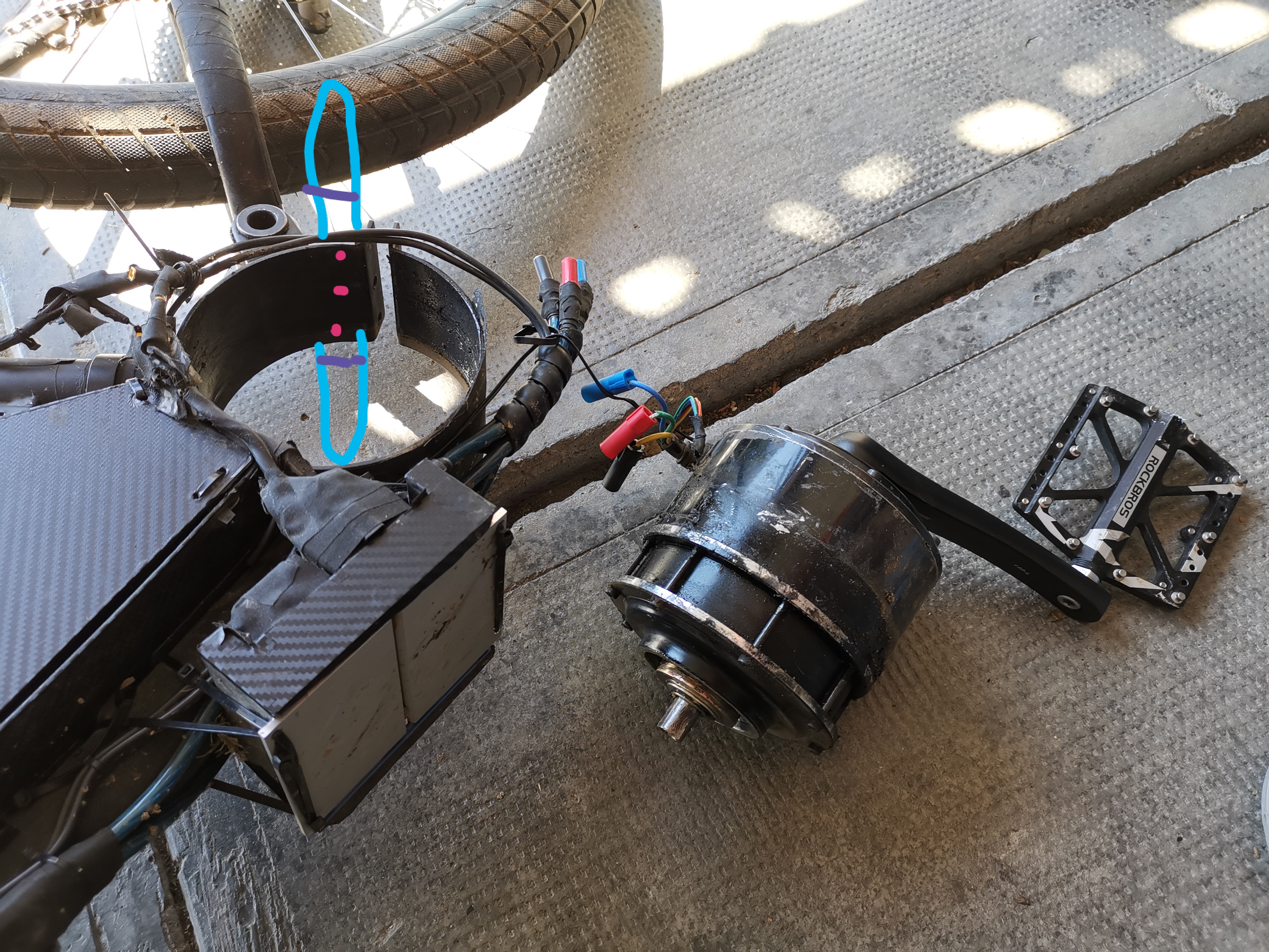
I see the shop foreman has come by for an inspection of the work.


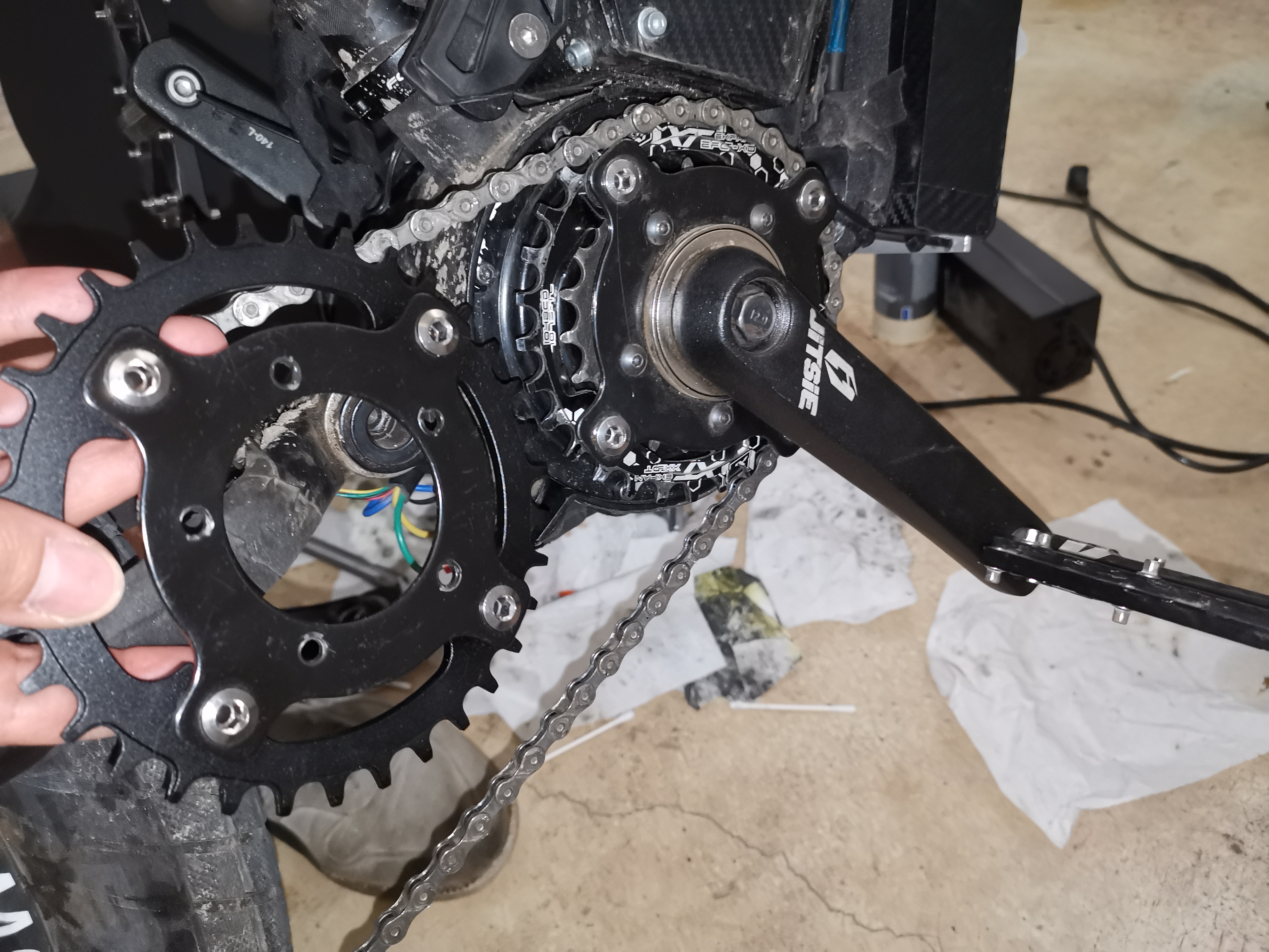
You should use enough spacers to almost touch the 22t internal chainring using a 30 or 32t narrow wide cog for a better chainline(closer to motor) and pedal position. I like 30t way better, has internal threads.
I have removed paint from around the motor where it touches the frame and used heat conductive paste on it. You have to use plenty as the plates that hold the parts togeather are a bit bigger in diameter than the body.
Also removed paint from the bottom partswhere I will put little heat sinks all around. Didn't remove it from the top. I didn't remove paint from the inside of the steel mount as it is quite porous, very good for accepting thermal compound and to avoid a metal reaction.
https://m.aliexpress.com/item/4000289214870.html
In addition to the termal adhesive pad, possibly superglue at the edges, I will use zip tipes around the motor to hold them.
Tommm said:You should use enough spacers to almost touch the 22t internal chainring using a 30 or 32t narrow wide cog for a better chainline(closer to motor) and pedal position. I like 30t way better, has internal threads.
I have removed paint from around the motor where it touches the frame and used heat conductive paste on it. You have to use plenty as the plates that hold the parts togeather are a bit bigger in diameter than the body.
Also removed paint from the bottom partswhere I will put little heat sinks all around. Didn't remove it from the top. I didn't remove paint from the inside of the steel mount as it is quite porous, very good for accepting thermal compound and to avoid a metal reaction.
https://m.aliexpress.com/item/4000289214870.html
In addition to the termal adhesive pad, possibly superglue at the edges, I will use zip tipes around the motor to hold them.
My motor is left side drive - right side crank - I will probably replace the 22t with a 219 sprocket - Left side will be 60T to 80T 219 or 53T - 75T 219 to start out which is similar to the ratio provided..
I want to get the motor as close to centre as possible, I will build the swing-arm to accommodate the best chain-line.
I was thinking about heat sinks too - thinking about getting something turned on a lathe - Or stacked lasercut rings
Chambers said:Tommm said:You should use enough spacers to almost touch the 22t internal chainring using a 30 or 32t narrow wide cog for a better chainline(closer to motor) and pedal position. I like 30t way better, has internal threads.
I have removed paint from around the motor where it touches the frame and used heat conductive paste on it. You have to use plenty as the plates that hold the parts togeather are a bit bigger in diameter than the body.
Also removed paint from the bottom partswhere I will put little heat sinks all around. Didn't remove it from the top. I didn't remove paint from the inside of the steel mount as it is quite porous, very good for accepting thermal compound and to avoid a metal reaction.
https://m.aliexpress.com/item/4000289214870.html
In addition to the termal adhesive pad, possibly superglue at the edges, I will use zip tipes around the motor to hold them.
My motor is left side drive - right side crank - I will probably replace the 22t with a 219 sprocket - Left side will be 60T to 80T 219 or 53T - 75T 219 to start out which is similar to the ratio provided..
I want to get the motor as close to centre as possible, I will build the swing-arm to accommodate the best chain-line.
I was thinking about heat sinks too - thinking about getting something turned on a lathe - Or stacked lasercut rings
The 22t is part of the motor, see
https://endless-sphere.com/forums/viewtopic.php?p=1569758#p1569320
But with spacers and the adaptor, you can place any bcd104 ring almost right ontop of it so it isn't a big issue.
If you are interested in 219 you can either make your own or cyc sell bcd104 holed 72,63,53t 219 rings. 53t is as big of a diameter as a 33t bike ring. Gearing wise, 53t is solid up front. Rear, 63 is good for combined use, 72 for a shread heavy and climb intensive setup.
Do you have an idea for a rear hub, how will you drive both sides of it?
Yes I should be able to bolt the 219 sprocket straight to the 22T - I would like a more elegant solution though so may make my own piece to replace the 22T piece (Not high priority but would be nice)
Paco supplied a 'disc brake flange adapter' which is a 104 bcd welded to a disc brake mount (middle of the second pic I posted earlier) which should be easy enough to mount a 219 sprocket to. I may have to look at an extra large rotor to get clearance like this...

I was looking at the cyc sprockets last night :lol:
Chambers said:Yes I should be able to bolt the 219 sprocket straight to the 22T - I would like a more elegant solution though so may make my own piece to replace the 22T piece (Not high priority but would be nice)
Paco supplied a 'disc brake flange adapter' which is a 104 bcd welded to a disc brake mount (middle of the second pic I posted earlier) which should be easy enough to mount a 219 sprocket to. I may have to look at an extra large rotor to get clearance like this...856004-547073-kit.jpg
I was looking at the cyc sprockets last night :lol:
Ah, the way you mount a bigger and replaceable sprocket to the 22t is with an adapter you have, just without the welded part. The 5 holes are the same holes as in the 22t and the standard sized freewheel.
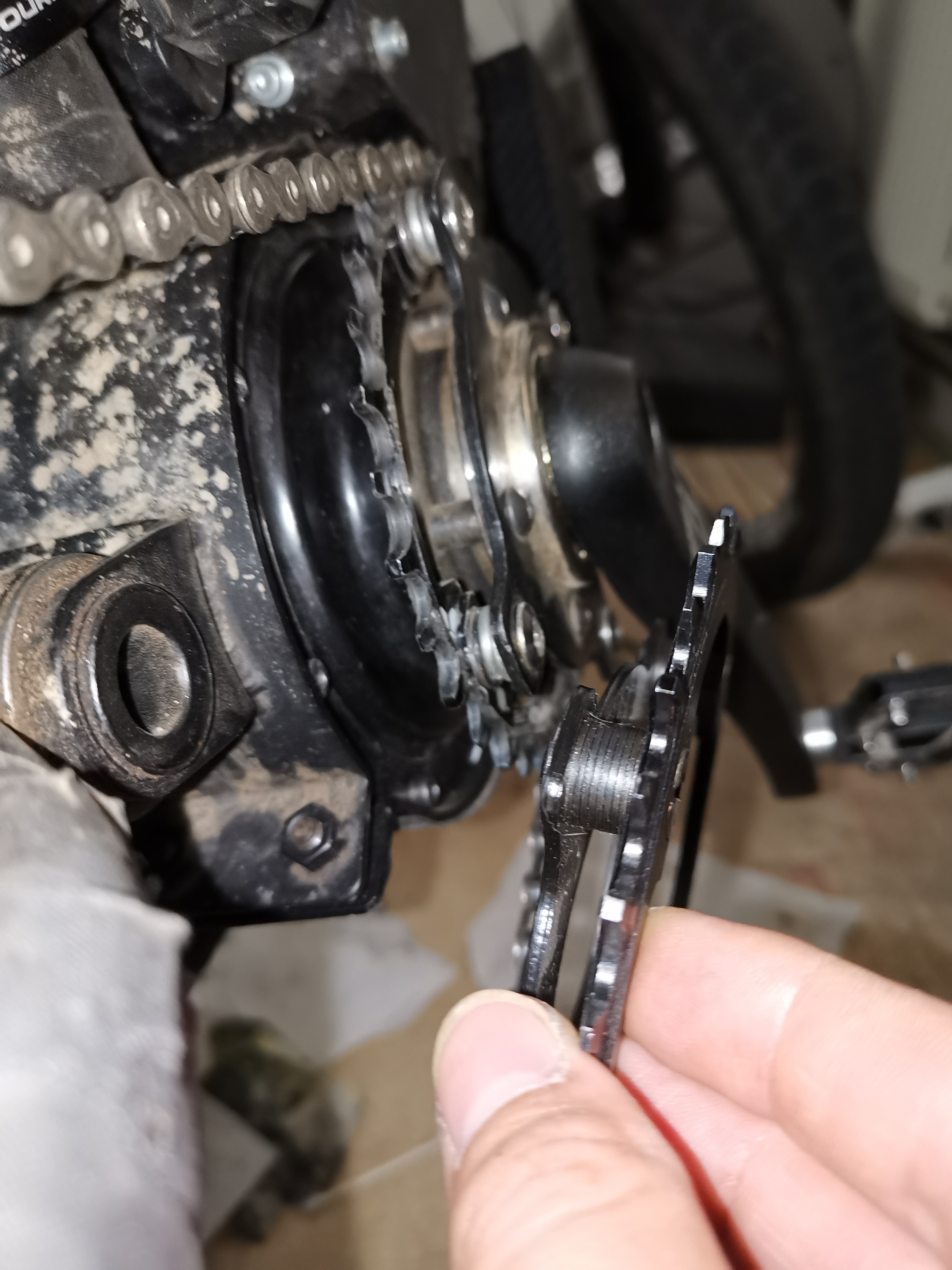
The 22t is inside of the adaptor, so close I can't get it in the shot. It is visible in the side shot though.
If you made a part like that, you could make one without teeth, meaning you could space the ring out even further inwards, improving the chain line.
Yes it does look like with this method only way of getting a bigger cog is a bigger brake disc, commercially you can get 223 now but stupid expensive.
Lucky the coaxial motor spins slow and has an internal reduction. So you are only looking for a 1.4x ish reduction. If you find a way to use a motor cog the size of a 22t bike cog, you wouldn't need any special brake equipment at all.
Chambers said:The 22t is part of the motor, see
https://endless-sphere.com/forums/viewtopic.php?p=1569758#p1569320
But with spacers and the adaptor, you can place any bcd104 ring almost right ontop of it so it isn't a big issue.
If you are interested in 219 you can either make your own or cyc sell bcd104 holed 72,63,53t 219 rings. 53t is as big of a diameter as a 33t bike ring. Gearing wise, 53t is solid up front. Rear, 63 is good for combined use, 72 for a shread heavy and climb intensive setup.
Do you have an idea for a rear hub, how will you drive both sides of it?
Yes I should be able to bolt the 219 sprocket straight to the 22T - I would like a more elegant solution though so may make my own piece to replace the 22T piece (Not high priority but would be nice)
Paco supplied a 'disc brake flange adapter' which is a 104 bcd welded to a disc brake mount (middle of the second pic I posted earlier) which should be easy enough to mount a 219 sprocket to. I may have to look at an extra large rotor to get clearance like this...856004-547073-kit.jpg
I was looking at the cyc sprockets last night :lol:
How will your pedals freewheel, if the adapter is only a plate? Hub is spinning therefore the chain on the pedal side too.
Tommm said:Chambers said:The 22t is part of the motor, see
https://endless-sphere.com/forums/viewtopic.php?p=1569758#p1569320
But with spacers and the adaptor, you can place any bcd104 ring almost right ontop of it so it isn't a big issue.
If you are interested in 219 you can either make your own or cyc sell bcd104 holed 72,63,53t 219 rings. 53t is as big of a diameter as a 33t bike ring. Gearing wise, 53t is solid up front. Rear, 63 is good for combined use, 72 for a shread heavy and climb intensive setup.
Do you have an idea for a rear hub, how will you drive both sides of it?
Yes I should be able to bolt the 219 sprocket straight to the 22T - I would like a more elegant solution though so may make my own piece to replace the 22T piece (Not high priority but would be nice)
Paco supplied a 'disc brake flange adapter' which is a 104 bcd welded to a disc brake mount (middle of the second pic I posted earlier) which should be easy enough to mount a 219 sprocket to. I may have to look at an extra large rotor to get clearance like this...856004-547073-kit.jpg
I was looking at the cyc sprockets last night :lol:
How will your pedals freewheel, if the adapter is only a plate? Hub is spinning therefore the chain on the pedal side too.
The pedals and motor output freewheel independently of each other - 2 freewheels. I'll post a vid when I have more time
Tommm said:Chambers said:The 22t is part of the motor, see
https://endless-sphere.com/forums/viewtopic.php?p=1569758#p1569320
But with spacers and the adaptor, you can place any bcd104 ring almost right ontop of it so it isn't a big issue.
If you are interested in 219 you can either make your own or cyc sell bcd104 holed 72,63,53t 219 rings. 53t is as big of a diameter as a 33t bike ring. Gearing wise, 53t is solid up front. Rear, 63 is good for combined use, 72 for a shread heavy and climb intensive setup.
Do you have an idea for a rear hub, how will you drive both sides of it?
Yes I should be able to bolt the 219 sprocket straight to the 22T - I would like a more elegant solution though so may make my own piece to replace the 22T piece (Not high priority but would be nice)
Paco supplied a 'disc brake flange adapter' which is a 104 bcd welded to a disc brake mount (middle of the second pic I posted earlier) which should be easy enough to mount a 219 sprocket to. I may have to look at an extra large rotor to get clearance like this...856004-547073-kit.jpg
I was looking at the cyc sprockets last night :lol:
How will your pedals freewheel, if the adapter is only a plate? Hub is spinning therefore the chain on the pedal side too.
Pedal chain still freewheels on the RHS of the hub also.
So 2 freewheels 'in' the motor LHS and one at the hub RHS.
An extra freewheel on the motor sprocket at the hub would probably make it a bit more efficient though.
Or is there something I'm missing?

I have, on cyclone 3k motor. Thermal polyurethane from farnell. Used up one 250ml 2-part bag for it. Mixed and poured in two parts - each motor end in different casting. In retrospect should have done in 3 parts - less messy.Chambers said:Has anyone done DIY motor potting?
1st casting, made a thin cardboard (and packing tape) tube for rotor hole. Resin started to seep trough windings. Should have used smaller quantity, just to seal the gaps, then pour later the 2nd part.
Other end went without problems, then windings were already cast full.
Used polyurethane (although is is nearly 2 times worse heat conductor than epoxy) because it's softer. Had doubts about epoxy and different thermal expansion of different materials (iron core, copper windings, aluminum motor shell).
Replaced (and tested) new hall sensors, replaced phase cables to biggest I could cram in there. Installed wrong temperature sensor which I never got around using (initial idea was to use separate custom display for motor/controller/battery temperature since stock c3k controller didn't support any external sensors). So cannot give any real data but I think it's well worth the effort.

minimum said:I have, on cyclone 3k motor. Thermal polyurethane from farnell. Used up one 250ml 2-part bag for it. Mixed and poured in two parts - each motor end in different casting. In retrospect should have done in 3 parts - less messy.Chambers said:Has anyone done DIY motor potting?
1st casting, made a thin cardboard (and packing tape) tube for rotor hole. Resin started to seep trough windings. Should have used smaller quantity, just to seal the gaps, then pour later the 2nd part.
Other end went without problems, then windings were already cast full.
Used polyurethane (although is is nearly 2 times worse heat conductor than epoxy) because it's softer. Had doubts about epoxy and different thermal expansion of different materials (iron core, copper windings, aluminum motor shell).
Replaced (and tested) new hall sensors, replaced phase cables to biggest I could cram in there. Installed wrong temperature sensor which I never got around using (initial idea was to use separate custom display for motor/controller/battery temperature since stock c3k controller didn't support any external sensors). So cannot give any real data but I think it's well worth the effort.
flir_20190701T074124.jpg
That's cool - Pardon the pun.
Did you happen to take any pics of the process?
Unfortunately not, was busy trying to contain the mess.Chambers said:Did you happen to take any pics of the process?
A few people here have potted the stators of various motors. Justin's thread here
https://endless-sphere.com/forums/viewtopic.php?t=48753
has some testing on that.
https://endless-sphere.com/forums/viewtopic.php?t=48753
has some testing on that.
Similar threads
- Replies
- 12
- Views
- 1,103
- Replies
- 58
- Views
- 5,809
- Replies
- 3
- Views
- 1,198
- Replies
- 4
- Views
- 542
- Replies
- 5
- Views
- 564