You are using an out of date browser. It may not display this or other websites correctly.
You should upgrade or use an alternative browser.
You should upgrade or use an alternative browser.
Custom frame for the Cyclone Coaxial motor
- Thread starter Chambers
- Start date
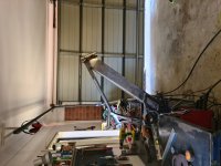
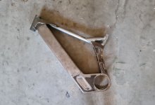
Got a bit more fab work done over the last couple of evenings, I was struggling to find 44mm id tubing for the head tube then I had a brain wave.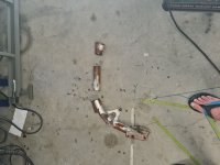 This old pit-bike frame looked to be close in dimensions
 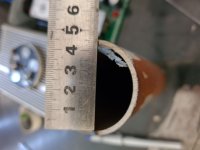 Perfect!
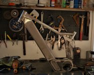
Then I took to adding some strength to the motor mount plates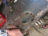 This is 20 x 3mm flat bar - I tacked it at the start then slowly bent around tacking as I went then welded them up
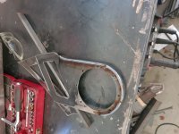
I had planned on TIG welding everything and leaving the welds (no sanding) but I got an air leak somewhere in my TIG torch/gas line which caused a bit of aggravation and a mess - I didn't take any pics of that bit - Was too busy being annoyed :lol:
Anyway long story short I went back to the trusty MIG (technically MAG but we don't need to have that discussion here) Got a few bits welded and mostly blended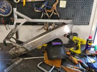
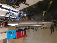
Someone asked on FB about the weight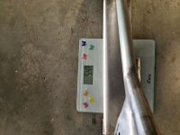 Excuse the butterfly scales :lol: that's 5.45 kg so far (That's about 12 pounds for the metrically challenged
  ) Hopefully should be able to keep it under 8kg including the swing-arm - A FUTR beta frame weighs 6.9kg for reference
 This old pit-bike frame looked to be close in dimensions
  Perfect!
Then I took to adding some strength to the motor mount plates
 This is 20 x 3mm flat bar - I tacked it at the start then slowly bent around tacking as I went then welded them up
I had planned on TIG welding everything and leaving the welds (no sanding) but I got an air leak somewhere in my TIG torch/gas line which caused a bit of aggravation and a mess - I didn't take any pics of that bit - Was too busy being annoyed :lol:
Anyway long story short I went back to the trusty MIG (technically MAG but we don't need to have that discussion here) Got a few bits welded and mostly blended

Someone asked on FB about the weight
 Excuse the butterfly scales :lol: that's 5.45 kg so far (That's about 12 pounds for the metrically challenged
 Pedrodemio
100 W
I've been silently following this build for a while
If there is a dream bike for me, is someday building a similar frame as that, can't wait to see the results
Well done Chambers
If there is a dream bike for me, is someday building a similar frame as that, can't wait to see the results
Well done Chambers
ThanksPedrodemio said:I've been silently following this build for a while
If there is a dream bike for me, is someday building a similar frame as that, can't wait to see the results
Well done Chambers
So I haven't completely disappeared - Apparently buying kids Christmas presents is more important than e-bike building  :lol:.
Anyway with limited funds available and still waiting on parts I built a place holder swing-arm with some scrap I had lying around.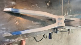 Room left over for some additional strengthening of the pivot point..
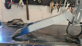
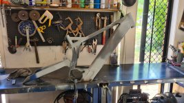
I will probably re-build this once I have the shock and hub in my hands (both on a VERY slow boat). Triangulation will be added between the pivot point and the hub and the rear most section will be replaced with some 6mm plate to hold the rear wheel.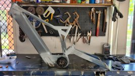
Anyway with limited funds available and still waiting on parts I built a place holder swing-arm with some scrap I had lying around.
 Room left over for some additional strengthening of the pivot point..

I will probably re-build this once I have the shock and hub in my hands (both on a VERY slow boat). Triangulation will be added between the pivot point and the hub and the rear most section will be replaced with some 6mm plate to hold the rear wheel.

Chambers said:Room left over for some additional strengthening of the pivot point..20210102_140123.jpg20210102_132914.jpg
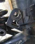
If you are using an axle hole interface for the pivot it is better to weld some bushing holder instead of frame to axle action. Otherwise even if greased the pivot hole will be a half inch up and ovalised if you check it next year. :lol:
haha wow thats some good work!Tommm said:Chambers said:Room left over for some additional strengthening of the pivot point..20210102_140123.jpg20210102_132914.jpg
If you are using an axle hole interface for the pivot it is better to weld some bushing holder instead of frame to axle action. Otherwise even if greased the pivot hole will be a half inch up and ovalised if you check it next year. :lol:
Screenshot_20210103_051947.jpg
Chambers said:haha wow thats some good work!Tommm said:Chambers said:Room left over for some additional strengthening of the pivot point..20210102_140123.jpg20210102_132914.jpg
If you are using an axle hole interface for the pivot it is better to weld some bushing holder instead of frame to axle action. Otherwise even if greased the pivot hole will be a half inch up and ovalised if you check it next year. :lol:
Screenshot_20210103_051947.jpg
What makes it better is the hole ovalised upwards on one side and downward on the other side. So there might have been some misalignment that is getting fixed (or getting worse) this way. When it gets long enough I plan on rounding the hole and making it take a press fit copper bushing. Maybe something harder.
BeachRider2016
100 W
Man, maybe someone can help you 3d print that part then cast in aluminum. It’ll be solid ! Great build btw, I’m definitely following.
Thanks! The plan was to make the first iteration out of steel for testing purposes then when I find the time to build my CNC router it'll be made from aluminium.BeachRider2016 said:Man, maybe someone can help you 3d print that part then cast in aluminum. It’ll be solid ! Great build btw, I’m definitely following.
Casting isn't a bad idea though! thanks
Chambers said:Bit of an update - Excuse the dodgy camera work...[youtube]R0r4oLNoZe4[/youtube]
I think for a progressive spring rate you want the linkage to shock interface to ramp up in the rate it moves per cm of wheel travel, the further the wheel is in the travel. Is it setup that way?
Tommm said:Chambers said:Bit of an update - Excuse the dodgy camera work...[youtube]R0r4oLNoZe4[/youtube]
I think for a progressive spring rate you want the linkage to shock interface to ramp up in the rate it moves per cm of wheel travel, the further the wheel is in the travel. Is it setup that way?
Yes
Just to elaborate, because of the shape of the top linkage (kind of banana shape) and the associated position of the bottom link the rate of leverage changes throughout the travel of the swingarmI think for a progressive spring rate you want the linkage to shock interface to ramp up in the rate it moves per cm of wheel travel, the further the wheel is in the travel. Is it setup that way?
raggertje
10 mW
Hi chambers, great project! I’m following your progression closely 
I’m designing an aluminum battery box that is I’m going to be weld in my specialized demo 8 downhill frame for a 17S11P or a 18S10P battery. How much space do you give the battery in the box? Have you allready thought of waterproofing the box?
Keep on the great build!
I’m designing an aluminum battery box that is I’m going to be weld in my specialized demo 8 downhill frame for a 17S11P or a 18S10P battery. How much space do you give the battery in the box? Have you allready thought of waterproofing the box?
Keep on the great build!
Lots of variables to take into account TBH, depends on how your battery gets into the frame box i.e. side load or from the bottom etc.raggertje said:Hi chambers, great project! I’m following your progression closely
I’m designing an aluminum battery box that is I’m going to be weld in my specialized demo 8 downhill frame for a 17S11P or a 18S10P battery. How much space do you give the battery in the box? Have you allready thought of waterproofing the box?
Keep on the great build!
I personally left enough room for a 5mm battery box (inside the down tube) on all sides when I did the CAD work but have ended up with a bit more. My battery box is going to bolted at the top and bottom of the down tube and kind of float inside the tube (not touch the sides) hope that helps
raggertje
10 mW
Yes I.m struggling with all those variables :wink: but there are challenges for 
I'm also going for a bottom load, more strength in the frame with a closed alu box although things aren't easy to reach. I'm thinking of a 5-10mm gap between battery and box and fill it with foam but it is a good idea to fix the battery with bolts. But then again your battery must be in some kind of case I think.
I'm also going for a bottom load, more strength in the frame with a closed alu box although things aren't easy to reach. I'm thinking of a 5-10mm gap between battery and box and fill it with foam but it is a good idea to fix the battery with bolts. But then again your battery must be in some kind of case I think.
Yes correct, I will have a box inside a box for my design - or perhaps a shrink wrapped battery attached to a plate.raggertje said:Yes I.m struggling with all those variables :wink: but there are challenges for
I'm also going for a bottom load, more strength in the frame with a closed alu box although things aren't easy to reach. I'm thinking of a 5-10mm gap between battery and box and fill it with foam but it is a good idea to fix the battery with bolts. But then again your battery must be in some kind of case I think.
My battery system idea is similar to a specialized kenevo (but with a much larger battery)
raggertje
10 mW
Chambers said:My battery system idea is similar to a specialized kenevo (but with a much larger battery)
Great idea, intergrating the skidplate/closing cap into the battery :thumb:
Thanks! Yes very similar to a 2006ish Turner DHR. Leverage ratio is about 3.07 - 66 mm stroke with around 204 mm wheel travel (2.6 inches x 8 inches)Buckow said:Amazing work. Out of curiosity what leverage ratios did you end up using? It looks like a nice rising rate linkage similar to the old Turner DH bikes.
I may need to add a heavier spring (currently 550lbs) but I'll wait and see how it all pans out.
Buckow said:Amazing work. Out of curiosity what leverage ratios did you end up using? It looks like a nice rising rate linkage similar to the old Turner DH bikes.
To be honest I must have redesigned the linkage at least 10 times - in the end I went with what felt about right with the view to modifying it in the future once I get a feel for how it rides
So I blew up my welder on Friday  a coil blew clean off the board.
Con: I have to buy a new welder (repairs is looking to be a similar price) and my project timeline is pushed back due to funds.
Pro: I get to buy a new welder - Im thinkin Acdc pulse TIG
Con: I have to buy a new welder (repairs is looking to be a similar price) and my project timeline is pushed back due to funds.
Pro: I get to buy a new welder - Im thinkin Acdc pulse TIG
Similar threads
- Replies
- 2
- Views
- 478
- Replies
- 12
- Views
- 2,043
- Replies
- 58
- Views
- 7,820


