CVT/Multi-Ratio Friction Drive Ideas

rhitee05 said:
All I can say is that'll be one heck of a friction drive. Do you plan to try and run it at multi-kW levels, or are you just using that nice motor because you have it lying around? :) That should really smoke a tire. What would you use as a roller?

Delta-wye is a nice way to get two different ratios without adding any mechanical complexity.

Tires are cheap! :mrgreen:

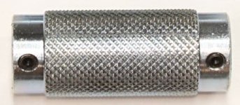
I'm not sure about the roller, but probably one of these:
DRIVEROLLER_125new.jpg

It is from this site, which somebody posted in one of these friction threads. I actually like this whole kit. I think it could be an inexpensive/simple conversion. Just figure out how to either mount a motor in place of the engine directly, or offset, via a reduction. Hmm... you could take a 3220 with a long 1/2" shaft, and mount it just like the gas engines mount, but you wouldn't have the freewheeling roller. It could do regen, though. :wink: The easiest way to have it freewheel would be to do what Todd is doing, and put a oneway needle bearing in the roller. I'm afraid that might not survive the power levels I'm looking for (3-4kW... maybe more... :roll: ) so I'd probably stick to the tried and true method of sticking an Eno inside an HTD pulley, or a #25 sprocket, and drive that from the motor. There doesn't need to be much of a reduction, if any, as an Astro 3220's sweet spot is about 7500 rpm, which means a top speed around 28 MPH with the 1.25" roller. I can do that with my existing 3220 7-turn (kV: 97 in wye; 168 in delta...) in delta mode on a "standard" RC setup (ICE 160 + 12s LiPos...).

I don't need a super-high top-speed, but I'd like it to hit at least 30 mph. What I'm more interested in is low-end torque and quick acceleration. :roll: :mrgreen: I'd start with a 12s LiPo setup, but as soon as somebody puts sensors on a 3220, I'm going to use one of Lyen's controllers, and an 18s2p pack.

-- Gary
 
I'm sidetracking my own thread, but that's okay - I'm allowed. :)

I wonder if you'd do better using a larger roller for a high-power drive. A larger roller (say 3" or 4") would have a larger contact patch with the tire and probably transmit power more effectively. Since you're planning to do belt drive already, there's no additional cost to make it a reduction to get the speeds correct for a larger roller. Reading that site, they do advertise it for use with engines up to ~4 HP, so maybe it'd be okay after all.

GGoodrum said:
What I'm more interested in is low-end torque and quick acceleration.

With that 1.25" roller you'll have whiplash-inducing acceleration up to 30 MPH! :-D Assuming an average power of 3 kW that would be a 0-30 time of 3 seconds for 100 kg.
 
Yes, sorry, I didn't mean to hijack your thread. :oops: I'll start a new one. I went ahead and ordered one of the full BikeMotorParts.com kits. Without the special roller shaft with the clutch bell on the end, which they were out of, the total price was $85. Amazingly low, for what you get. If I wanted a non-powder-coated plain version, it is only $75.

Anyway, I thought I'd get one, and then figure out how to add the 3220, either directly replacing the engine, or with a reduction.

-- Gary
 
I actually think the straight cone roller would be more practical. You'd have simple linear motion that can be handled with a wormscrew - or even a small servo or linear atuator. Just as easily a combo cable/spring system could be used. Also, you would have a straightforward and consistent pressure/tension system to keep the roller snug against the tire - which would be difficult to manage with a pivoting, curved roller system.
 
michaelplogue said:
I actually think the straight cone roller would be more practical. You'd have simple linear motion that can be handled with a wormscrew - or even a small servo or linear atuator. Just as easily a combo cable/spring system could be used. Also, you would have a straightforward and consistent pressure/tension system to keep the roller snug against the tire - which would be difficult to manage with a pivoting, curved roller system.

Actually, the whole point of the pivoting "curved Roller" is to make the contact / pressure consistent without the need for a sliding mechanism !
One simple pivot point.
 
The main reason for the curved roller is exactly as Hillhater said. I also think that a pivot mechanism is easier to make and requires less precision than a linear mechanism like a worm screw. I can use lever action and a cheap RC servo to move it back and forth with no fussy details.

The disadvantage of the curved roller, I think, is that the decrease in radius (dr/dx if you prefer) gets sharper as you get toward the small end. Recently I'm thinking that it might be beneficial to make the radius of curvature (the roller shape) slightly larger than the pivot radius. That would make the curve a little less sharp and also provide a little more contact force at the low gears when the torques will probably be higher.

I also think a mechanism like Gary describes is just the ticket. A Kepler-style free-swinging roller, with the pivot point on the motor shaft so the roller can swing into the tire by inertia. A one-way bearing setup is also a good option, but I'm less mechanically-inclined than EVTodd. I'd be afraid of not getting something quite right, but a Kepler-type mechanism seems easier.
 
I am wondering if there isn't some off the shelf RC unit that senses motor rpm and sends signal accordingly. Maybe a gizmo that changes the pitch of the prop according to rpm or something like a trim tab on a boat that adjusts as the boat goes faster. I do think that you will want to spend most of your time at one end or the other on the roller and the cone shape is just for seamless transition between the two so in essence you could design it as a two speed system.

Michael,
I'm really liking your cone drawing, never thought about slanting the motor up to slide the roller across at the same level, F'ing brilliant!
 
etard said:
I am wondering if there isn't some off the shelf RC unit that senses motor rpm and sends signal accordingly. Maybe a gizmo that changes the pitch of the prop according to rpm or something like a trim tab on a boat that adjusts as the boat goes faster.

There's probably something, I haven't really looked. To be honest, if electronic is the way to go I'd rather build my own anyhow. That would let me design the control loop myself and tweak it as needed. Plus I could do other neat things using the same MCU. Current-based throttle, cruise control, etc. :)
 
Seems like a good time to talk about control.

Mechanical control would be nice, but I don't think its practical. I think the mechanism would be either overly complex or difficult to tune - or both. I don't have the mechanical skills to be confident it would do what I want.

So, electronic control. Adds some components, but I think its still fairly simple and the parts are cheap.

Algorithm:
The strong point of electronic control - it can do whatever I want. I think a PID loop based on motor RPM is the best bet. The setpoint for the control loop is adjusted based on the throttle input, so it works something like the automatic transmission in a car. You could do a non-linear mapping via lookup table if that proved more optimal, but linear is simple and probably good. So, the control loop will adjust the ratio to keep the motor running in its most efficient range through the whole range of speeds, but will also adjust the ratio to provide more torque on-demand. The exact parameters would require some tuning, but that's a functional description of the algorithm.

This algorithm would work best with a torque-based throttle, which is part 2. At this point we've got an on-board MCU with access to the throttle signal, so we might as well use it for the ESC interface instead of a servo tester. While we're doing that, add a very simple current sensor to an analog input and now we can do a current-based throttle. There's a very good approach which uses an inner current loop for direct throttle input and an outer speed loop for cruise control. Now we're talking. :-D It's like an extra $5 of hardware and a few hours of programming time to do this, very worth it.

Basic setup:
- RC servo to rotate drive around pivot via lever action
- Simple MCU, probably Arduino for low cost and simple programming
- A couple magnets and a hall sensor to do RPM count on roller, more magnets and 2nd hall sensor for wheel RPM count (cruise control)
- Shunt and a little bit of analog circuitry for current sense
 
rhitee05 said:
Mechanical control would be nice, but I don't think its practical. I think the mechanism would be either overly complex or difficult to tune - or both. I don't have the mechanical skills to be confident it would do what I want....
:shock: :shock:
complex ? ..never !
just think how the mechanical derailleur works....its doing exactly what you need, moving a pivoting gear change mechanism.
Its practically a ready made solution, cheap , and easily available at any LBS ( or dumpster !)

I wouldnt attempt to electrically automate the shift system until you have proven the principle works in practice mechanically.
 
Hillhater said:
complex ? ..never !
just think how the mechanical derailleur works....its doing exactly what you need, moving a pivoting gear change mechanism.
Its practically a ready made solution, cheap , and easily available at any LBS ( or dumpster !)

I wouldnt attempt to electrically automate the shift system until you have proven the principle works in practice mechanically.

Sorry, I meant automatic mechanical control. Something torque or centrifugal-force based. It seems like that mechanism would likely be either simple but difficult to adjust, or easy to adjust and very complex. I prefer simple and easy to adjust! :)

And yes, the first stage would need to be a purely manual proof-of-concept. An indexed gear-shift would indeed be very useful for this. I would do that first with nothing but the roller and pivot mechanism - no motor or anything. Just to prove that the mechanism works, there isn't too much friction, etc.
 
Hillhater said:
rhitee05 said:
Mechanical control would be nice, but I don't think its practical. I think the mechanism would be either overly complex or difficult to tune - or both. I don't have the mechanical skills to be confident it would do what I want....
:shock: :shock:
complex ? ..never !
just think how the mechanical derailleur works....its doing exactly what you need, moving a pivoting gear change mechanism.
Its practically a ready made solution, cheap , and easily available at any LBS ( or dumpster !)

I wouldnt attempt to electrically automate the shift system until you have proven the principle works in practice mechanically.


I agree, a simple twist type gear shift would be the ticket. I have seen a lot of people invent things and when you are trying to prove a concept, the best POSSIBLE scenario is to simplify and then work out the fancy stuff. Otherwise it ends up being a project that never really happens.. Just my $.02 :) Really good ides though with he cone, I like it! a simple pivot in the right place and you are gone!
 
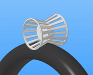
The clutch drive on an ATV or Snowmachine has variable speed system where the width of the shivs change. Would using two stepped cones facing each other be able to do the job, if the steps collapsed into each cone as increased rpm was needed, work? Can anyone understand the hairbrained idea?
 
Miles said:
Anything like this hairbrained concept, Gordo? :)
I got an old drill-press kinda like that. (flanges are on the large side) I rekon fabbing those would be a challenge.
 
Miles;
That is a better idea and with proper springs and weights, is very much worth working on in my view. Building it will be quite a challenge. :mrgreen: :mrgreen:
 
If you could make that work, it would be genius! not too hard to build I would think, you would just have to make one end of one of them able to be removed... possibly have each big end just the fingers sticking out, and then have a compression type piece that threads on over it and locks the fingers together?
 
Back
Top