The first bike I built was a mid drive and it was ultimately a frustrating experience for me due to the chain frequently coming off. I built a couple increasingly powerful and heavy hub drive bikes until reaching the point where bicycle tires, brakes and suspension were over-taxed by the speed and weight of the bike. I know there are solutions for those things, but I wanted to step back and re-evaluate my goals. There's a place for speed and power, but at some point it can't properly be called a bicycle any longer. I wanted an ebike that I could:
1. Conveniently take with me on public transit.
2. Contribute a meaningful amount of human pedal power towards propelling.
3. Not overtax the bicycle components from the speed and weight due to the electric drive.
I decided to aim for a maximum continuous 300 watts of assist from the motor, assuming I could comfortably maintain 100 watts contribution by pedaling myself. I did a bit of research and found that 400 watts should get me in the 40 - 50 kph speed range, with the power required to go faster ramping up quickly due to air resistance at this point. This seemed an acceptable top speed for city traffic and cycling in general.
I was inspired by the simplicity, light weight, and efficiency of Kepler's friction drives and chose a 6374 170 kV skateboard motor based on diameter, kV, and bearing quality.
http://www.freerchobby.cc/e_product...less-DC-Motor-for-Electric-Skateboard-23.html
Although it is capable of more power than I needed I couldn't find any low kV motors of large enough diameter to make the 'gear' reduction appropriate for the low speeds I was aiming for.
I found a good quality used folding bike (Dahon) with an aluminum frame on kijiji for $500. It came with a 7 speed Nexus internally geared Shimano hub, which was a nice unplanned bonus. Here's a picture of the friction drive with a smaller motor before the 6374 skateboard motor arrived.
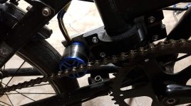
I used this VESC from HobbyKing capable of 50 amps 50 volts for the motor controller.
https://hobbyking.com/en_us/turnigy-sk8-esc-v4-12-for-electric-skateboard-conversion-w-bec.html
The friction drive worked fantastic in dry conditions. Unfortunately as soon as I had to deal with rain and snow I could only deliver 50 to 100 watts before the motor started slipping on the tire. I added a rough sandpaper finish with grip tape around the motor housing to increase friction on the tire, but it did not help enough and wore down my tires fairly quickly. You can see the rubber worn away and reinforcement showing through in this image.
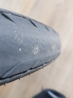
After a winter's worth of riding, this is how the motor mount looked. It had functioned, but not very well in wet conditions and I wanted an improvement.
![20200406_170417[1]small.jpg 20200406_170417[1]small.jpg](https://endless-sphere.com/sphere/data/attachments/147/147861-c215fef7a40c6c1d317d0ffcf071ea4a.jpg)
I was inspired by Tom Stanton's youtube series showing his development of a mid drive ebike based around a 3d printed pulley. I would have been skeptical that a 3d printed pulley would last, but his videos convinced me that it could work. While I would have preferred a chain and sprocket, I thought that for low power a belt and pulley would be sufficient. Furthermore, 3d printing lends itself more easily to pulleys than to sprockets.
I reverse engineered my rear wheel using calipers and a measuring tape. Apparently there are better methods. It took me a few tries but I got the pulley to fit onto the spokes nicely and zip tie in place. I believe there might be some hidden mounting holes for a disc brake on this hub, but I haven't investigated as my spoke mounting solution works for now.
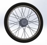
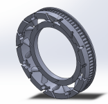
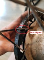
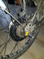
I discovered there were going to be some chain-line issues while doing the CAD. In order for the drive belt to clear my chain stays I needed to mount the motor fairly high up, and the motor shaft and end of the drive pulley would stick out precisely where my bicycle chain would pass through.
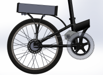
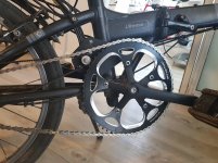
The solution: A larger front chainring. I found that a 60 tooth sprocket would give me the right amount of clearance, while also increasing the speeds at which I could continue to pedal-assist at. With the original front sprocket I would need to pedal at an inhumanly high rate to continue assisting at 50 kph. With the 60 tooth sprocket, 90 rpm at the pedals will move me at 50 kph. I could kill two birds with one stone-- solve my chain line clearance issue and improve my gear ratio for higher speeds as well. The Nexus-7 hub would in its lowest gear still provides a reasonable gear reduction for pedaling at low speeds.
Since 60 tooth chain rings are not common, I asked a friend to machine me the sprocket. In order to test that my CAD was suitable I printed one to make sure it would work with my single-speed chain.
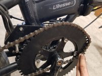
I ended up finding an off-the-shelf 60 tooth chain ring that shipped quickly from ebay anyway, and might not end up using the sprocket my friend machined for me. Sorry Mark!
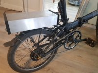
Here's the bike with belt drive installed.
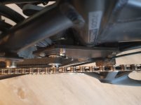
I used a 12 tooth drive pulley (the lowest I could find, and my gear ratio is still higher than I'd like). It uses 9 mm wide HTD or GT2 5mm belt (the tooth profile is very similar, though I think GT2 and GT3 are supposed to perform a bit better. My rear pulley is 81 tooth. Although I would like to, I can't go much larger on the rear pulley or wider on the belt because it won't clear the chain stays if I do. I may need to add a belt tensioner idler pulley near the motor to prevent the belt slipping. This is something I wish I had realized earlier in the process, because to add it now will probably mean getting a new motor mounting plate waterjet cut.
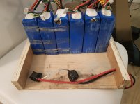
I improved my battery box from the rough wooden one I used over the winter as well. The mounts for the wooden battery box came dangerously close to damaging my batteries. The plastic housing has been chafed away, but the balance on the cells is still good.
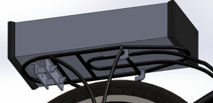
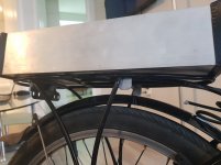
I found a standard size of aluminum rectangular tube that just required some 3d printed end caps and designed a quick-release mechanism for mounting it on my luggage rack. This should allow me to park my bike and easily only take my battery somewhere for charging and safe-keeping. The quick-release mechanism still needs some work to be feasible and functional. In the mean time the box is fastened by a screw through the former rear reflector mount on my luggage rack.
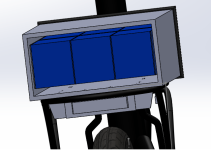
The prismatic Turnigy 5s 5ah cells I have slide into the box very nicely and can be removed easily for access. There's extra room for a BMS, contactor on/off switch, status LEDs, etc. The wall thickness of the aluminum is higher than I'd like but I couldn't find any box tube with thinner walls. This makes it heavier than it needs to be. This is something I still want to improve on.
1. Conveniently take with me on public transit.
2. Contribute a meaningful amount of human pedal power towards propelling.
3. Not overtax the bicycle components from the speed and weight due to the electric drive.
I decided to aim for a maximum continuous 300 watts of assist from the motor, assuming I could comfortably maintain 100 watts contribution by pedaling myself. I did a bit of research and found that 400 watts should get me in the 40 - 50 kph speed range, with the power required to go faster ramping up quickly due to air resistance at this point. This seemed an acceptable top speed for city traffic and cycling in general.
I was inspired by the simplicity, light weight, and efficiency of Kepler's friction drives and chose a 6374 170 kV skateboard motor based on diameter, kV, and bearing quality.
http://www.freerchobby.cc/e_product...less-DC-Motor-for-Electric-Skateboard-23.html
Although it is capable of more power than I needed I couldn't find any low kV motors of large enough diameter to make the 'gear' reduction appropriate for the low speeds I was aiming for.
I found a good quality used folding bike (Dahon) with an aluminum frame on kijiji for $500. It came with a 7 speed Nexus internally geared Shimano hub, which was a nice unplanned bonus. Here's a picture of the friction drive with a smaller motor before the 6374 skateboard motor arrived.

I used this VESC from HobbyKing capable of 50 amps 50 volts for the motor controller.
https://hobbyking.com/en_us/turnigy-sk8-esc-v4-12-for-electric-skateboard-conversion-w-bec.html
The friction drive worked fantastic in dry conditions. Unfortunately as soon as I had to deal with rain and snow I could only deliver 50 to 100 watts before the motor started slipping on the tire. I added a rough sandpaper finish with grip tape around the motor housing to increase friction on the tire, but it did not help enough and wore down my tires fairly quickly. You can see the rubber worn away and reinforcement showing through in this image.

After a winter's worth of riding, this is how the motor mount looked. It had functioned, but not very well in wet conditions and I wanted an improvement.
![20200406_170417[1]small.jpg 20200406_170417[1]small.jpg](https://endless-sphere.com/sphere/data/attachments/147/147861-c215fef7a40c6c1d317d0ffcf071ea4a.jpg)
I was inspired by Tom Stanton's youtube series showing his development of a mid drive ebike based around a 3d printed pulley. I would have been skeptical that a 3d printed pulley would last, but his videos convinced me that it could work. While I would have preferred a chain and sprocket, I thought that for low power a belt and pulley would be sufficient. Furthermore, 3d printing lends itself more easily to pulleys than to sprockets.
I reverse engineered my rear wheel using calipers and a measuring tape. Apparently there are better methods. It took me a few tries but I got the pulley to fit onto the spokes nicely and zip tie in place. I believe there might be some hidden mounting holes for a disc brake on this hub, but I haven't investigated as my spoke mounting solution works for now.


I discovered there were going to be some chain-line issues while doing the CAD. In order for the drive belt to clear my chain stays I needed to mount the motor fairly high up, and the motor shaft and end of the drive pulley would stick out precisely where my bicycle chain would pass through.

The solution: A larger front chainring. I found that a 60 tooth sprocket would give me the right amount of clearance, while also increasing the speeds at which I could continue to pedal-assist at. With the original front sprocket I would need to pedal at an inhumanly high rate to continue assisting at 50 kph. With the 60 tooth sprocket, 90 rpm at the pedals will move me at 50 kph. I could kill two birds with one stone-- solve my chain line clearance issue and improve my gear ratio for higher speeds as well. The Nexus-7 hub would in its lowest gear still provides a reasonable gear reduction for pedaling at low speeds.
Since 60 tooth chain rings are not common, I asked a friend to machine me the sprocket. In order to test that my CAD was suitable I printed one to make sure it would work with my single-speed chain.

I ended up finding an off-the-shelf 60 tooth chain ring that shipped quickly from ebay anyway, and might not end up using the sprocket my friend machined for me. Sorry Mark!
Here's the bike with belt drive installed.


I used a 12 tooth drive pulley (the lowest I could find, and my gear ratio is still higher than I'd like). It uses 9 mm wide HTD or GT2 5mm belt (the tooth profile is very similar, though I think GT2 and GT3 are supposed to perform a bit better. My rear pulley is 81 tooth. Although I would like to, I can't go much larger on the rear pulley or wider on the belt because it won't clear the chain stays if I do. I may need to add a belt tensioner idler pulley near the motor to prevent the belt slipping. This is something I wish I had realized earlier in the process, because to add it now will probably mean getting a new motor mounting plate waterjet cut.
I improved my battery box from the rough wooden one I used over the winter as well. The mounts for the wooden battery box came dangerously close to damaging my batteries. The plastic housing has been chafed away, but the balance on the cells is still good.

I found a standard size of aluminum rectangular tube that just required some 3d printed end caps and designed a quick-release mechanism for mounting it on my luggage rack. This should allow me to park my bike and easily only take my battery somewhere for charging and safe-keeping. The quick-release mechanism still needs some work to be feasible and functional. In the mean time the box is fastened by a screw through the former rear reflector mount on my luggage rack.


The prismatic Turnigy 5s 5ah cells I have slide into the box very nicely and can be removed easily for access. There's extra room for a BMS, contactor on/off switch, status LEDs, etc. The wall thickness of the aluminum is higher than I'd like but I couldn't find any box tube with thinner walls. This makes it heavier than it needs to be. This is something I still want to improve on.


