CVT/Multi-Ratio Friction Drive Ideas

rhitee05

10 kW
Joined
Apr 7, 2009
Messages
841
Location
Upstate SC
I wanted to branch off the >2 ratio drive concepts from JennyB's thread to avoid confusion and hopefully attract more interest. The goal of this thread is to discuss ideas for multi-ratio and CVT-like friction drives. I have a couple of ideas and hope others will chime in with comments or their own ideas. I'm hoping we'll be able to come up with a design promising enough to try a prototype!

Motivation:
Several people have been having good luck with their single-speed friction drives, but experience with a variety of drive types has shown that having gears available (electrical or mechanical) is always better. Especially when using RC ESCs, its useful to be able to avoid low-speed, high-current operation. A few two-gear ideas are being tossed around in the thread linked below. If two gears are good, more are better! The more available ratios, the closer more we are able to operate the drive at a sweet spot of efficiency. I think a useful multi-ratio drive has to span a range of gears at least 2:1. For reference, the 9-speed cluster on my bike has a range of 2.7:1.

Original thread link:
http://endless-sphere.com/forums/viewtopic.php?f=28&t=21342&start=0

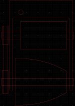
Here is a quick drawing of the original concept I had:
CVT Concept.PNG

It's a very simple design. The roller surface is a circular arc around the pivot point (the small circle at upper left). As the whole assembly rotates, the radius of the roller gets smaller and the ratio gets higher. I've drawn it with the motor mounted above and belt drive, but you could also do a direct-drive. An advantage to the belt is it gives you another reduction step so there's more freedom in the choice of roller diameter and motor Kv. A potential issue with this concept is that there will be some difference in speed across the contact patch with the tire. This might not be an issue, or it could cause some additional wear. Distance to the tire does not change so the pressure would remain constant.

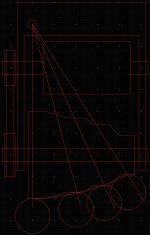
To address that problem, I came up with a second concept:
Multi-ratio Concept.PNG

This concept has several discrete ratios rather than being a CVT. There's a section of constant radius for each ratio, so this would avoid the differential speed issue from the CVT. The section widths and spacings are chosen to try and follow the pivot arc so the distance to the tire is about the same. The mount would have to move slightly to absorb the changes is distance as the gears shift. A disadvantage is that the contact point with the tire will rotate from the top slightly toward the side as the drive goes to the highest ratio. I also think the control mechanism would have to be more complex. The CVT can be controlled closed-loop, so the actuator doesn't need to know the position of the pivot, it only needs to know when it hits the min/max stops. For the multi-ratio drive you would need to use sensors to lock the drive in one of the fixed positons.

Construction:
I'm a fan of wood for ease of prototyping and because I don't have access to a machine shop. It would be relatively easy to make a wood roller on a lathe to any arbitrary profile. A hardwood like oak would probably be the most suitable. The finished roller could then be repeatedly dunked in polyurethane to build up a nice, thick coating. The resulting surface should be soft enough to get good grip and not cause much wear on the tire, but hard enough to last for a while. Skateboard, roller skate, etc. wheels are made of polyurethane, after all. When the coating does wear, the roller can be sanded and re-coated. A wood roller would also be lighter and have less inertia than a solid metal roller of similar radius.

My initial concept would probably use a roller with 4" max diameter, 4" long, and based on an 8" radius to the pivot point. Such a roller would require about 2500 RPM to reach 30 MPH. That's probably a bit low to be driven directly by an RC motor, but a slight reduction in the belt drive (less than 2:1) would bring it in-line. Something around ~1.7:1 would work for a 170 Kv motor at 24V. I haven't come up with a way yet to make the ratio self-adjusting, so an RC servo and some simple control electronics would be required.
 
Although a belted drive would add some bulk and cost (compared to direct drive), I very much agree that it would also add many desirable options. There are many reasons I opted to use a 1/2" shaft in my recent project, one of the reasons is the availablility of industrial parts for a 1/2" shaft.

HTD toothed high-RPM belts with a 5mm pitch (distance between the peak of one tooth and the next) are readily available, and the pulleys can be had in many diameters that range from 1.25" to 4.50" (20T - 72T).

The "Shaft-Loc" system is similar to a collet. Two parts are threaded into each other, and together they expand to clamp the shaft to the metal center of the pulley. There are shaft adaptation sleeves that allow an 8mm or 10mm motor shaft to become 1/2", so these pulleys can be used on them.

79002092.JPG
 
Eric, One of the things I like about the belted drive is that, your 'most desired' motor may not be available (or simply too expensive to get soon). In that instance, a pulley ratio change can allow your second choice of motor to be used for a while.

Using fine-grained hardwood dipped in polyurethane is brilliant! I really like your second design with gear-steps. I think having at least 3 speeds would solve a LOT of the recent problems, and would allow the compact and affordable range of ESCs to become much more reliable.
 
talk about turning something so simple into something complex...lol.

i really like this idea of multi-speed friction drives. the second concept looks promising rhitee. the way youll change gears on something like this will always baffle me. would the whole drive unit be on something like a track that slides back and forth from left to right via something like a worm drive gear or something similar like that?
 
def215 said:
talk about turning something so simple into something complex...lol. ...
..... the way youll change gears on something like this will always baffle me. would the whole drive unit be on something like a track that slides back and forth from left to right via something like a worm drive gear or something similar like that?

Read /look at it again !. the whole unit is on a pivot.
A simple Derailleur type mechanism could be used to "shift" ratios.
 
It seems an automatic-shift based on motor torque, should be manageable.

The motor mounted on a radially moving plate that has an arm connected to the pivot's mounting plate ... or something like that... :?
 
Or just use a small roller and match the motor kv to the top speed you want.

I've talked about this before but my original plan when I made my first Kollmorgen drive was to use a roller with 2 or three different "speeds". If you absolutely have to use a specific motor I can see maybe trying a multi-diameter system. I just don't see the point if you're using an rc motor. Use a small diameter roller so you have great hill climbing plus the added benefit of keeping the motor in it's efficiency sweet spot while cruising.

I think a lot of people on here are still thinking about the whole reduction issue. It's already done for you with friction drive.

It's friction drive! The most simple, basic, no-nonsense form of moving something. I think we're getting into Rube Goldberg territory here.

All that being said I'm still looking forward to seeing what you come up with. As much as I think it's unnecessary I do think it's a cool concept.
 
TylerDurden said:
It seems an automatic-shift based on motor torque, should be manageable.

I agree that something like that should be doable. If the roller axle was canted very slightly, for example, it would generate a torque around the pivot point proportional to the drive torque on the tire. You could use a spring so that the deflection varies based on torque. I think you would want to arrange it so the return no-torque position is high gear, and any torque will pull it down into a lower gear.

My question here is, is torque-based gearing desirable? I had assumed it would be better to vary the ratios based on speed to keep the motor running in the efficient range of RPM. Perhaps the torque-based system would do that well enough? Anyone with a better mechanical intuition than me?

I did a little reading up on the scooter variator CVT drives. It seems that the ratio there is controlled by a combination of RPM and torque.
 
Buried somewhere in my useful stuff is a mains AC motor fitted with a conical, aluminium roller that has almost exactly the same profile as in your first drawing rhitee. It came from a potters wheel. Unfortunately I don't have the rest of the wheel to check how it was mounted
 
Any sort of variable system is obviously going to be more complicated than a fixed-ratio setup. Several people have made very nice single-speed friction drives (Kepler and EVTodd, among others) and seem to have good luck with them. What I'm trying to figure out here is, can we make a variable-speed drive that's not much more complex? Can we make it simple enough that the upside makes it worth the effort?
 
Your first roller profile reminds me of a prop cone from rc airplanes, perhaps you can find one for large scale planes that will work off the shelf, hell those are ready fit for rc motors anywayz.

I like the swing pivoting action of the first drawing, I think the best way to make it work manually might be a motor rpm readout on the handlebars that would give the rider input into the ideal setting for the roller to keep the motor in the sweet spot. Although, I can see this getting anoying, always monitoring rpm and tweaking roller position, especially in stop and go traffic. Automatic solution would be best, or two speeds to switch between.

Todd,
Show us video of you doing wheelies on your 30mph ebike, and I will be sold on one roller does all. :lol: :wink:
 
I'm guessing that most of the basic auto-CVT schemes are RPM based, variating via centrifugal force.

My initial notion was torque on the motor mount could be a more simple means of control.
 
etard said:
Show us video of you doing wheelies on your 30mph ebike, and I will be sold on one roller does all. :lol: :wink:

I will. In fact, I ordered a small digital camera for playing around with the bike. To that point though, I honestly don't care if anyone believes how well it works or not. What I have cared about all along was showing people a simple (and really cheap) way to make an electric bike. I've even offered to give the drive to people on here to prove how well it works, but I've been turned down every time.

Like I've said before, I just get excited about how easy and simple it is and want people to know. I do realize though that everyone has different ideas which is why I love this forum.

Anyway. I'll get off the soap box now. I'm done trying to convince people. I don't mean to hijack a thread.
 
TylerDurden said:
I'm guessing that most of the basic auto-CVT schemes are RPM based, variating via centrifugal force.

Yes, I think that you're correct. I'm having a hard time coming up with any simple way to use centrifugal force to regulate this design without making it too complex. I have no issues going to electronic control, but a mechanical setup would be much more in the KISS philosophy!

TylerDurden said:
My initial notion was torque on the motor mount could be a more simple means of control.

Ah, I think I see now. You mean using the reaction torque on the motor mount to push against a lever or somesuch. Interesting idea, I'll have to ponder that. It would likely be the simplest option.
 
EVTodd, no worries. FWIW, I like your design! :)
 
It occurs to me that, if belt drive is used, then a spring-loaded idler pulley could be used to adjust based on the belt tension, i.e. torque.
 
rhitee05 said:
It occurs to me that, if belt drive is used, then a spring-loaded idler pulley could be used to adjust based on the belt tension, i.e. torque.
Yeah, I'm not sure if a feedback loop would be worse there or at the motor.

The centrifugal systems may offer better feedback suppression.
 
KISS.. guys ! ... automating anything means more complexity, cost and potential failure points.
Use a simple mechanical control, cable operated to a Derailleur type shifter ( twist grip ?)
Your ears will tell you when to shift ! ( this is an RC motor after all :lol: )
 
Hillhater said:
KISS.. guys !
Yes, simple is good, done and proven. Automatic-shift can be done. How well.... should be considered.


As for hysteresis to reduce feedback loops, perhaps a spring detent (bullet-catch) to delay shifting points would be sufficient.
 
Hillhater said:
KISS.. guys ! ... automating anything means more complexity, cost and potential failure points.
Use a simple mechanical control, cable operated to a Derailleur type shifter ( twist grip ?)
Your ears will tell you when to shift ! ( this is an RC motor after all :lol: )

It might be okay for a system with 2 or a handful of gears, but I don't think a manual shift is practical for a CVT setup. It would simply be impossible to manage both the throttle and shifter at the same time. Even if it was physically possible you'd be so distracted that it would be a serious hazard - the control mechanism for a CVT would have to be automatic. The question here is whether a simple mechanical setup can be devised, or if electronic control is better suited.
 
Tyler,

I think I understand what you're saying and it makes sense. I understand controls theory, I just have to translate the mechanical into electrical in my head! :) An underdamped system would be bad. I think using a very soft-start throttle action would probably help somewhat, but maybe not enough. I don't think I have the mechanical modeling know-how to figure out if that would be a problem other than just building a prototype to test.

It's starting to sound like an electronic system might be a better bet. It would be a little more complex, but I think more predictable, and more importantly I'm confident that I could tune the system to be nice and stable.

Here's what I'm envisioning: A small MCU of some sort would control a small RC servo, which would actuate the drive via a lever. A simple magnet-Hall combo would provide feedback of drive RPM for a simple control loop. With a little extra effort, the MCU could also take a throttle input and provide the correct signals to the ESC. It would be a pretty easy thing to set up, and the control parameters would be easy to adjust to get the desired results.
 
rhitee05 said:
I think I understand what you're saying and it makes sense. I understand controls theory, I just have to translate the mechanical into electrical in my head! :) An underdamped system would be bad.
Yeah, crappy automatic trannys bounce between gears when the load is right at a shift point. Shifts solely based on motor torque could have that effect. Anything that makes the gears a little "sticky" could help.

(Just thinkin out loud here, anyway.)
 
If I ever get some "free" time, what I want to try is take half of one of Matt's drive (the "foot", seat tube clamps and motor mount plate...), with one of the 3220s with the shaft going out both ends of the motor. I'd then have two connected plates, with bearings, on either end of the motor. This section would rotate on the motor axis. At the other end would be the roller, with a belt or #25 chain drive reduction, between the motor and the roller shaft. This whole reduction/roller assembly would hang down from the motor shaft. Like Kepler's outrunner design, this would be spring-loaded to pull the roller away from the tire, so that no one-way bearing is required for the roller. The motor torque, when it is on, "pulls" the roller into a locked position. This is the most clever part of Kepler's design, in my opinion. :)

For achieving two-speeds, I will use delta-wye switching on the 3220, which it is well suited for, as all six wires are brought out of the motor. Wye mode will be used to start out, and when it gets past its max efficiency point, I'd switch to delta mode. This gives an effective ratio change of 1.73:1.

Anyway, this is my plan. :) Getting time to execute this plan might be another story. :roll:

-- Gary
 
All I can say is that'll be one heck of a friction drive. Do you plan to try and run it at multi-kW levels, or are you just using that nice motor because you have it lying around? :) That should really smoke a tire. What would you use as a roller?

Delta-wye is a nice way to get two different ratios without adding any mechanical complexity.
 
Back
Top