
Upgrading stock 40A Cyclone controller with a KT36/48ZWSHKT-NP01X Controller and KT LCD8S Display from the below link. Using a 48v 12ah battery. The original motor, controller, throttle, battery have worked for years although I don't ride that much.
Started by just matching colors of phase, hall sensor, and throttle wires and immediately ran into issues. The display first errored on the throttle and figured that three wire difference out fairly quickly. Oh, and no manual or wiring diagram for the new KT Controller. Have asked from seller and KT with no response. Now I get a Motor Position Fault. I have been researching for a few days and found several articles on how to wire and determine what wires provide what functions. Unfortunately nothing has worked. I have even opened old and new controllers to try and determine what wires should be connected and I think I am getting closer but just need a little more help. I have attached pics of the new controller and old controller diagram. Current wiring that results in a motor position fault error when a touch of throttle is applied.
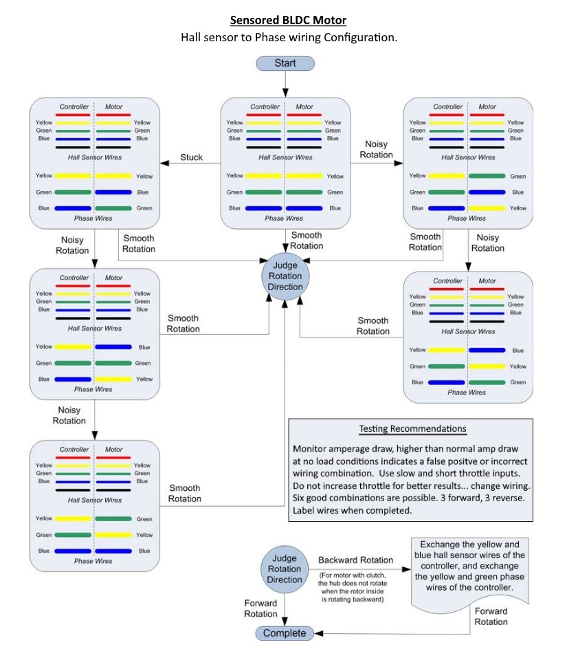
Motor Controller
Phase - Matching up A,B,C designations on Circuit Boards
Green Blue
Yellow Green
Blue Yellow
Hall Sensor - Followed same color scheme
Green Blue
Yellow Green
Blue Yellow
Black Black
Red White - Or does this need to be Red to Battery +. When disconnected and controller powered up, Red measured 4.2v and White 4.8v. White on the controller board does say x5 vs Red says hv
Do I need Battery + into the controller on Red? Old controller required it but no labels or docs on this controller.
If anyone has any experience with Cyclone 3k's and KT Controllers I would appreciate any and all suggestions.


Controller and Display
https://www.aliexpress.com/item/225...!12000027411931223!im&gatewayAdapt=4itemAdapt
Started by just matching colors of phase, hall sensor, and throttle wires and immediately ran into issues. The display first errored on the throttle and figured that three wire difference out fairly quickly. Oh, and no manual or wiring diagram for the new KT Controller. Have asked from seller and KT with no response. Now I get a Motor Position Fault. I have been researching for a few days and found several articles on how to wire and determine what wires provide what functions. Unfortunately nothing has worked. I have even opened old and new controllers to try and determine what wires should be connected and I think I am getting closer but just need a little more help. I have attached pics of the new controller and old controller diagram. Current wiring that results in a motor position fault error when a touch of throttle is applied.
Motor Controller
Phase - Matching up A,B,C designations on Circuit Boards
Green Blue
Yellow Green
Blue Yellow
Hall Sensor - Followed same color scheme
Green Blue
Yellow Green
Blue Yellow
Black Black
Red White - Or does this need to be Red to Battery +. When disconnected and controller powered up, Red measured 4.2v and White 4.8v. White on the controller board does say x5 vs Red says hv
Do I need Battery + into the controller on Red? Old controller required it but no labels or docs on this controller.
If anyone has any experience with Cyclone 3k's and KT Controllers I would appreciate any and all suggestions.
Controller and Display
https://www.aliexpress.com/item/225...!12000027411931223!im&gatewayAdapt=4itemAdapt

 Given this is a mid-drive vs hub motor, is there any reason not to believe I have a bad hall sensor vs a wiring issue? If it is a sensor, do I need to pull it apart and find the part number or are all Cyclone 3000's the same and use the Honeywell SS41F?