Designed a first version of my flip flop hub drive

Thank you for the encouraging words :D

thepronghorn said:
I would suggest not trusting two halves of your frame clamp to line up perfectly and give you a nice aligned shaft. Just attach your bearing/motor mounting plate to one of the clamps and the other side just holds it to the frame.

This is what I ended up doing indeed :) Simplicity.

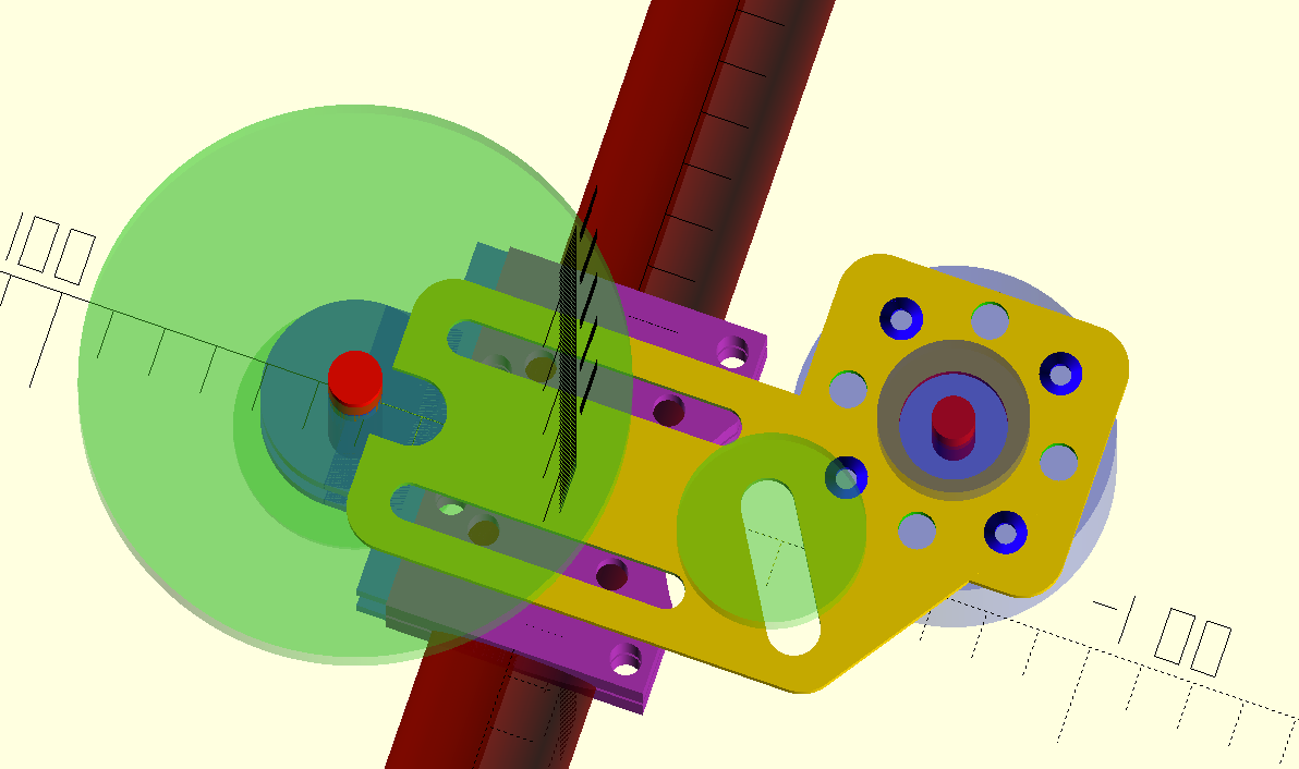
I chatted up with a friend which works as a cnc engineer and he gave me some great tips plus a range for the price, which is about half as cheap as I thought, so that's great. He gave me the advice to use 6mm 7075 aluminium for the mounting plate this would give me enough strength for the motor and the vibrations. However this wouldn't leave me enough room on the motor shaft because it's only 25mm long. So I moved the adjustment slots to the frame mount side. (reducing it to only 3 parts to have manufactured!) Not entirely sure if I'm going to leave this much adjustment room in the final design, but we'll see what the guys at his shop have to say when I send in the designs. In the current designs I also have pretty big rounded on the corners, I'm probably going to make that smaller too so I can drill a hole in one of the corners on the motor side to mount some....hall sensors :shock: However still a lot of research need to be done for that, Burtie's topic has been of great inspiration: https://endless-sphere.com/forums/viewtopic.php?t=15686 (And this one: https://endless-sphere.com/forums/viewtopic.php?p=281714#p281714) In the current version I also went trough every single measurement to make sure it's correct, some things had some 'unexplainable' offsets :roll: and made separate mounts for the top and bottom frame mount, to get rid of some of the exces bolt holes.

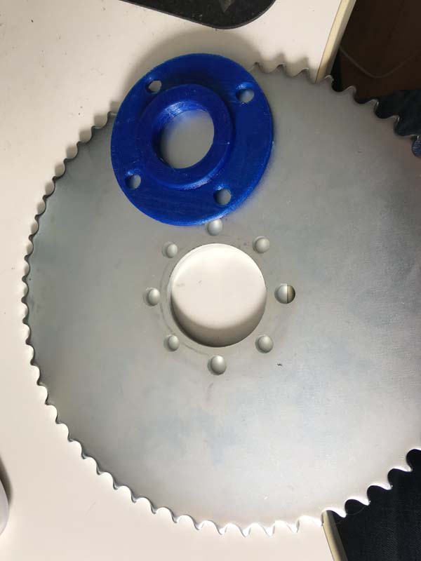
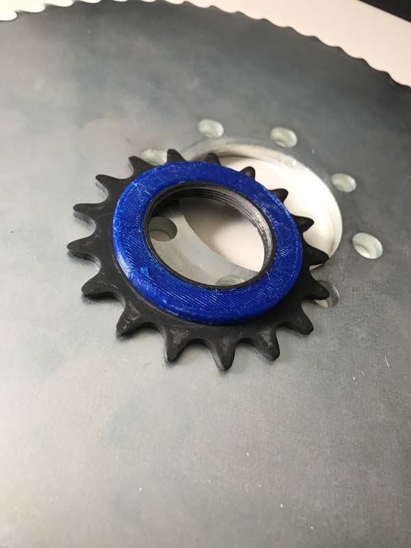
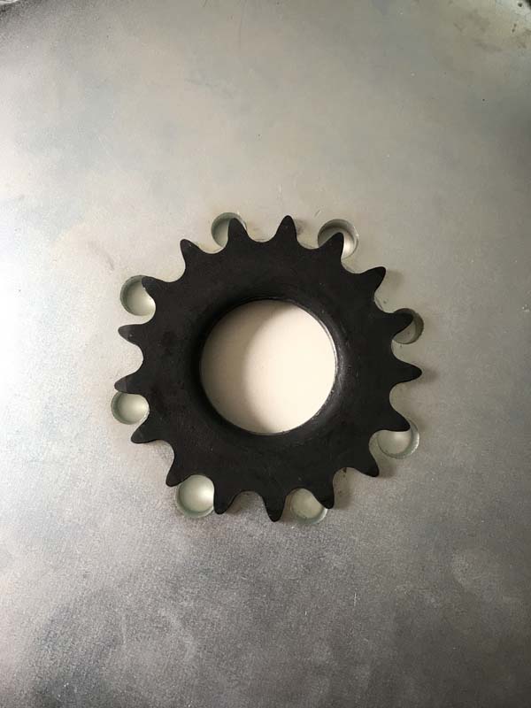
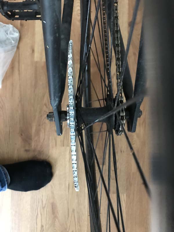
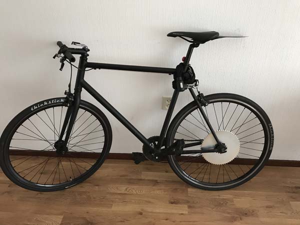
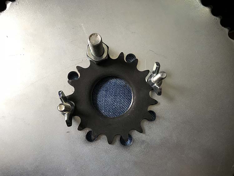
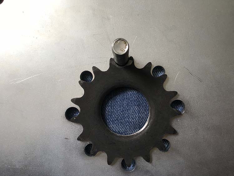
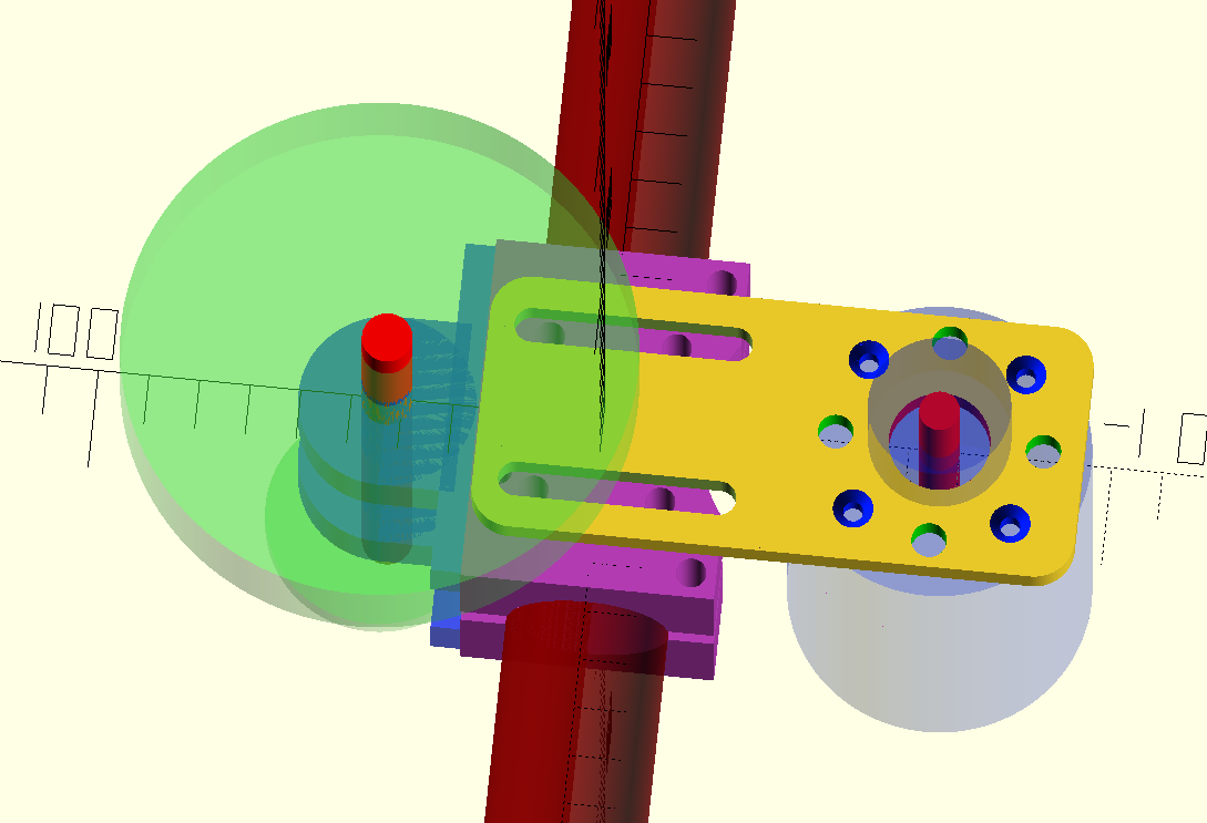
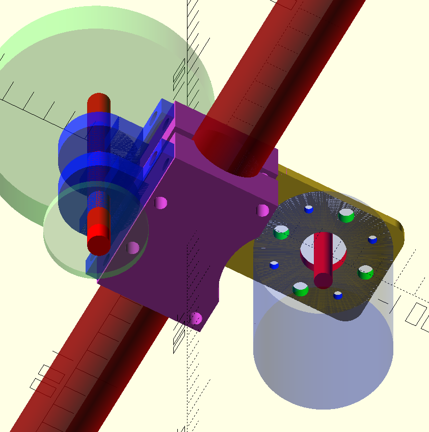
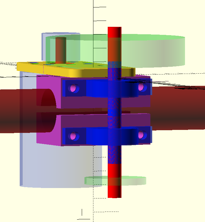
Anyway, here are some up to date pics:

7h76MBH.png

gH5uxpq.png

oN5FQZL.png


I hope to get this shipped off before the end off the week, still need to make some adapters though, and my bike rolling before the end of the month...with some blessings from the shipping gods

This week, finally, my VESC motor controller came in. Not the first one I ordered over a month ago, no, the second one from ebay arrived right on schedule. The first one is still missing...somewhere...and the guys from that store are very bad at communicating apparently... :( However, I have finally been able to fire up my engine and play around with my setup with my batterypack. It's freaking awesome :mrgreen:
 
I have finally been able to fire up my engine and play around with my setup with my battery pack. It's freaking awesome

I still remember sleeping on a friends couch, trying to find a job in anew city, and...I got some RC components to work as a friction drive. I went around showing everybody I knew. The 24-hr / 7-day "EV grin" almost made my face hurt...

A year from now, there are 12-step programs for ebikers you can join.

"Hi...my name is eTim, and I am an ebike addict"

"Hi, eTim"

(*sips free coffee, looks around the room, and realizes that he is not alone...)
 
Is there a private sub forum which I'm not aware about? Perhaps if I get started on the program early I have a better chance at rehabilitation :mrgreen:

I couldn't contain myself, had to mock this idea up with a tensioner pulley:
ffmEDyK.png


But I already decided I'm going to keep it simple with the first version, the mounting system allows me to relatively easily swap the 'yellow plate'.

... I also just realised I need to check clearances below the big gear wheel and the frame mount, and check if I have enough room for a bolt head :!:
Eitherway, steady progress :)

Quick question, I use a gear pulley on my motor in which the set screws are in the center of the pulley, in between the gears. Can it hurt to have half of the height of the pulley be without a shaft in it and the set screws mounted on the very tip of the motor shaft? Would the added stress because of the seesaw effect put more wear on the bearing?
 
Been a while :mrgreen:

Finally found someone who wanted to make my parts in the low quantity I wanted, so those are under way. Also I bought a left hand side freewheel sprocket adapter from electricscooterparts.com but I can't get it to fit :( Every inside dimension is the same as the sprocket that came on that side, m34x1.0 thread and all, threaded in the right direction etc....can't get it threaded on :( So I guess I'll have a m43x1.0 adapter made also, and lose the freewheel there which kinda stinks.
I've got the coming 3 weeks off, and hope to have made at least a first test drive before the end of my vacation :)

Thinking some more at it, it's probably threaded the wrong way
 
Hey Avner, thanks for your reply, how do you measure that? I'm not familiar with the imperial system. If I measure the inside diameter of both sprockets they're both 34mm, the stock one is just right hand thread and the adapter left hand thread. Basically I'd need a right hand thread anti clockwise engaging freewheel. I went wrong in thinking I needed a left side hub (well I need, but..) because normally you'd flip your wheel over if you would want to use that sprocket, making it right hand side etc.
 
1⅜"-24 thread can be expressed in metric terms as 34.9x1.058.
 
eTim said:
Hey Avner, thanks for your reply, how do you measure that? I'm not familiar with the imperial system. If I measure the inside diameter of both sprockets they're both 34mm, the stock one is just right hand thread and the adapter left hand thread. Basically I'd need a right hand thread anti clockwise engaging freewheel. I went wrong in thinking I needed a left side hub (well I need, but..) because normally you'd flip your wheel over if you would want to use that sprocket, making it right hand side etc.


eTim,
I've reread your recent posts.
If I understand correctly, you tried to screw a LH freewheel (FWM-150 on electricscooterparts) which has LH threads to your flip flop hub which has RH threads (on both sides).
Of course LH female threads won't fit to RH male threads even if they have the same diameter and pitch.
I brought up the whole metric/imperial issue because I thought you had machined a new part with metric threads.

For a left side chain you need a left hand freewheel. LH freewheels must have LH threads and RH freewheels RH threads, otherwise they would unscrew themselves once engaged.

Avner.
 
Hi guys,

Thank you for your replies, you are right, it is probably not m34x1.0. Sorry for the late reply, I had been side tracked with other small projects because I got a little discouraged, I don't think I have a real good way to determine the threading, since I don't have the right tools for it. Besides the freewheel hub adapter not having the right threading, I also mismatched the bolt spacing with the big-ass sprocket 60t I bought. However I think I've got a solution for mounting it, it's without a freewheel and...it's kinda crazy, but tell me what you think :mrgreen:

gGJysiM.jpg


So at first I 3d printed this adapter to see if I had the dimensions right. I would have had this turned from metal, this however still didn't solve the main issue, I didn't know the right threading. So I could have had it cut in m34x1.0 in the correct direction, but then I still had the chance it was the wrong size.

So then I grabbed the original sprocket that used to be on that side of the weel and made a spacer to center it in the new larger sprocket...

Mx7Fxv7.jpg

2iajMDl.jpg


Sadly the sprocket is 17t so it doesn't line up nicely with all the bolt holes, but if I get a right sized bolt in there, that could work right.....? :mrgreen: With a bit of grinding I could get at least 2 bolts in. The 3D printed spacer would make sure it's centred on the axle, perhaps I could get a simple donut machined from aluminium for longevity, but I guess 3D printing 10 myself will always be cheaper

MiLzaet.jpg


There's enough spacing at the frame, only thing is that it's touching the spokes at the hub, however since the sprocket should not rotate it should be fine I reckon. I got my hands dirty and laid down the chain I have to check for clearances, and it seems fine, passing past the tire with more then enough :mrgreen:

EijOwdu.jpg


LOOK AT IT! :mrgreen: :mrgreen:

If this works out, I will be able to send out my order to get the motor/frame mount made, and when that comes in, we should be able to take a first test drive
1 more issue I have now is that the sprocket is too thick for my chain...checked everything for chain size except sprocket width. Sigh. The sprocket is huge anyway, weighs 2+kg (1 pound?) and is 6 mm thick.
If I get stupid enough I will mount the sprocket on the wheel, and peddle it forward while grinding down the teeth of the sprocket evenly. Perhaps with an angle grinder and a grinding disc. If I get that stupid, I'll make sure to make a video of it.
If I come to my senses I'll just buy a wider chain :mrgreen:

Edit;
Did some more testing...seems like this will work. Printing a new spacer now, the old one had half a mil play on the sprocket.
This is only a test fit but, I can bolt it up like this:
R3Irzxh.jpg

Top bolt is a m10 bolt, had to slightly massage the hole in the big sprocket. With only the top m10 bolt in there is 0 play left to right on the black sprocket! The other 2 bolts are m6 right now, but I will get some m7, those will fit better. Those bolts are there to make sure the sprocket doesn't tilt when tightening the big bolt. Here's another look:
qCYMoGL.jpg

You can see I could fit an other 2 bolts closer to the big bolt, but I don't think I will need those.
I'll have to grind some bolt heads down to make them slim and fit in between the spokes, but that isn't the biggest of issues.

What do you guys think? Really curious if you reckon this will work (and for longer then 100 meters). It seems pretty solid to me
 
Hi eTim.

*As been mentioned before, standard freewheel thread is 1⅜"-24 thread not M34x1.0. Regardless, If you want to make sure that the parts will match, it is best to supply the machinist with the part that will thread to the new part he makes.

*If you thread a cog (fixed or freewheeling) on the left side of the bike to a right hand threaded hub and apply power, it will unthread.

*If you have no freewheels in the system, you pretty much eliminate the possibility to pedal (when the motor is not powered).

*My advise is to invest the time in locating correct off the shelf parts before committing to a build. It seems to me that your hub, sprockets and adapters won't be able to transfer power from the chain to the wheel.

Avner.
 
ferret said:
Hi eTim.

*As been mentioned before, standard freewheel thread is 1⅜"-24 thread not M34x1.0. Regardless, If you want to make sure that the parts will match, it is best to supply the machinist with the part that will thread to the new part he makes.

*If you thread a cog (fixed or freewheeling) on the left side of the bike to a right hand threaded hub and apply power, it will unthread.

*If you have no freewheels in the system, you pretty much eliminate the possibility to pedal (when the motor is not powered).

*My advise is to invest the time in locating correct off the shelf parts before committing to a build. It seems to me that your hub, sprockets and adapters won't be able to transfer power from the chain to the wheel.

Avner.

Hi Avner,

The thing what confuses me about that threadsize is that this is a european bought bike, and it's 'made' in Germany, there isn't a non metric bolt on the bike. I'm still too stubborn to admit that the hub is that size :mrgreen: , partially because I can't seem to find a size chart that shows me outside diameter, etc. Every measurement, as far as I can measure with my limited ability, of m34x1.0 fits. But thank you for re-iterating once again, I'll spend some more time tonight researching thread sizes in imperial sizes

About the unthreading, good point, I should have mentioned that there is a counter clockwise threaded locking ring, that presses against the sprocket, so unthreading is not a concern. Having no freewheels is indeed a concern, but I do have a motor controller that gives me advanced control of the motor, I've known that not having a freewheel was an issue from the start, but for the first version is acceptable, I plan to evolve this system over time
 
The entire world has settled on British freewheel threading as standard. That's 1.37"-24, with 60 degree threads. Decades ago, you could find Italian and French threaded freewheels with different thread sizes, but those are gone now. The Italian one was close enough to be sometimes compatible with British-- 35mm x 24tpi with 55 degree threads, I think? (Yes, Italian bike threads mix metric diameters with inch pitches. Fa bella figura!)

There has never been M34x1 freewheel threading. If it fits, it's because it's too small and the excessive clearance allows it to fit. You can thread an M9x1 axle into a 3/8"-26 axle nut, or a 3/8-26 axle into an M10x1 nut, but if you try to tighten it, it will strip out immediately. That's the situation you're making for yourself if you don't use the right thread.

The only metric freewheel threading still used is M30x1, which is used for 13t to 15t single freewheels.
 
eTim said:
About the unthreading, good point, I should have mentioned that there is a counter clockwise threaded locking ring, that presses against the sprocket, so unthreading is not a concern. Having no freewheels is indeed a concern, but I do have a motor controller that gives me advanced control of the motor, I've known that not having a freewheel was an issue from the start, but for the first version is acceptable, I plan to evolve this system over time

A counter clockwise (LH) lock ring can't be threaded to a clockwise (RH) male thread.

Advanced control of the motor is nice, as long as you don't get a drained battery, a mechanical or electrical failure in the middle of nowhere and can't get home...

BTW, a 16T cog will probably be easier to bolt to the 8 hole pattern on your big cog.

Avner.
 
Back
Top