Designed a first version of my flip flop hub drive

eTim

1 mW
Joined
Apr 20, 2017
Messages
16
Location
Utrecht, the Netherlands
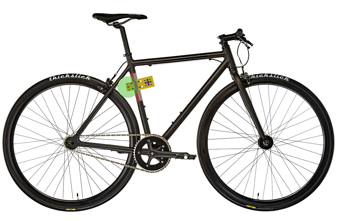
...and I've never done anything like this before, so I would love to get some feedback! About a month ago I started seriously working on my ebike project that I've had the idea for since I first got my flip flop hub bike. Basically, and I'm sure it's been done before, is to use the unused sprocket on the left side of the hub to power my bicycle. I specifically want to make everything myself, because that's the challenge and the fun of it. Let's get on to my idea for the drive.

4sue8Jr.png


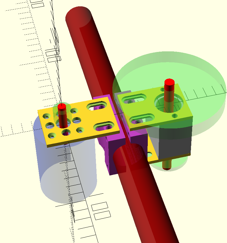
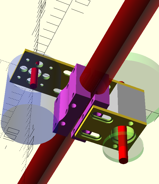
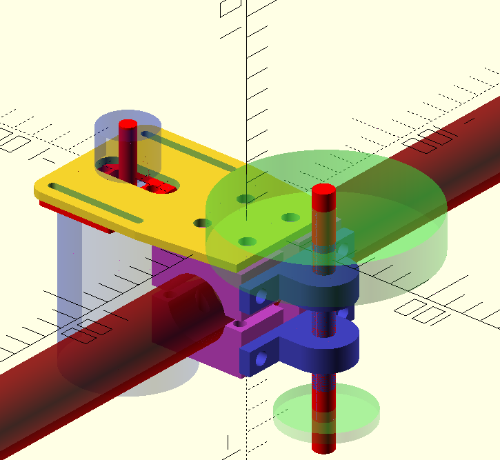
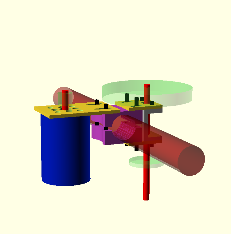
This is the current version 1.0. In the image the motor is mounted on the right and the reduction shaft is on the left, driven by a large gear wheel. (I'm sure this is not entirely to scale, but I did make the frame tube the same diameter and tried to line it up as best I can)
It would be a belt driven system from the motor to the trough shaft, and from there chain drive to the rear sprocket. Currently I'm planning on a 6:1 ratio on the belt drive and a 42 tooth rear sprocket, with easily swapped sprockets on the trough shaft :wink: So a lot like the recumpence drive, I guess, but then self made.

CPIeZe8.png


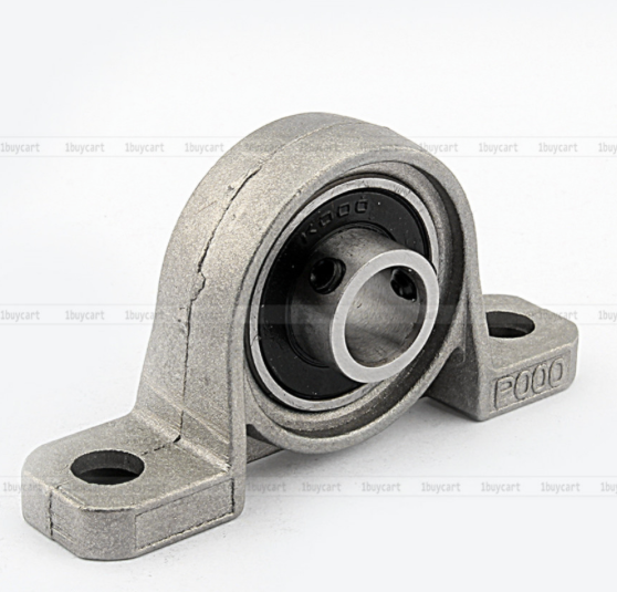
Some context: the motor is blue, it's shaft is red, the yellow plates are, well, plates, the red tube is the bycicle frame tube, the green wheels are the gear wheels, the grey U shape is the trough shaft mount, this would house bearings to hold the trough shaft of the reduction drive and finally the black tubes are temporarily there to show screw positions and how far they go into the material.

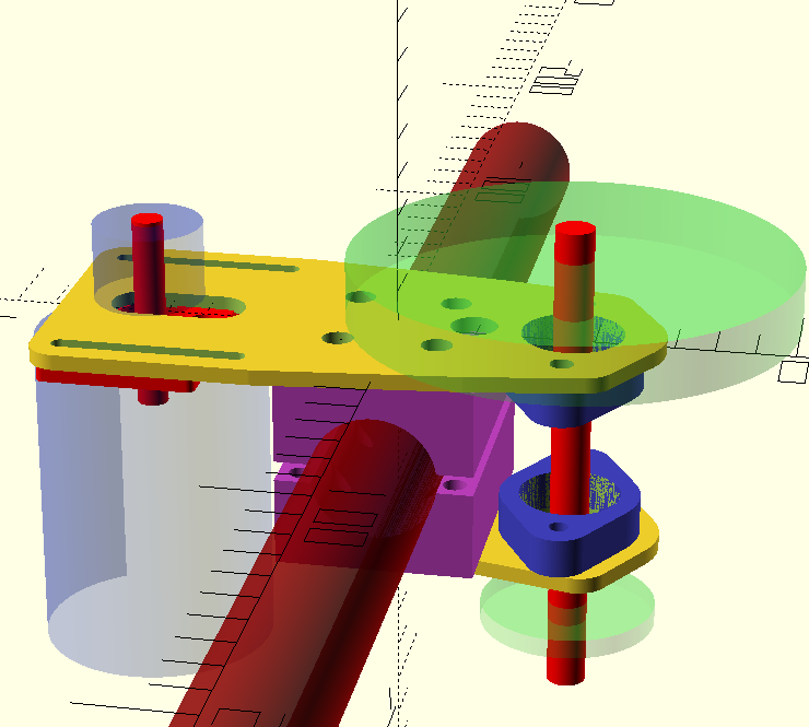
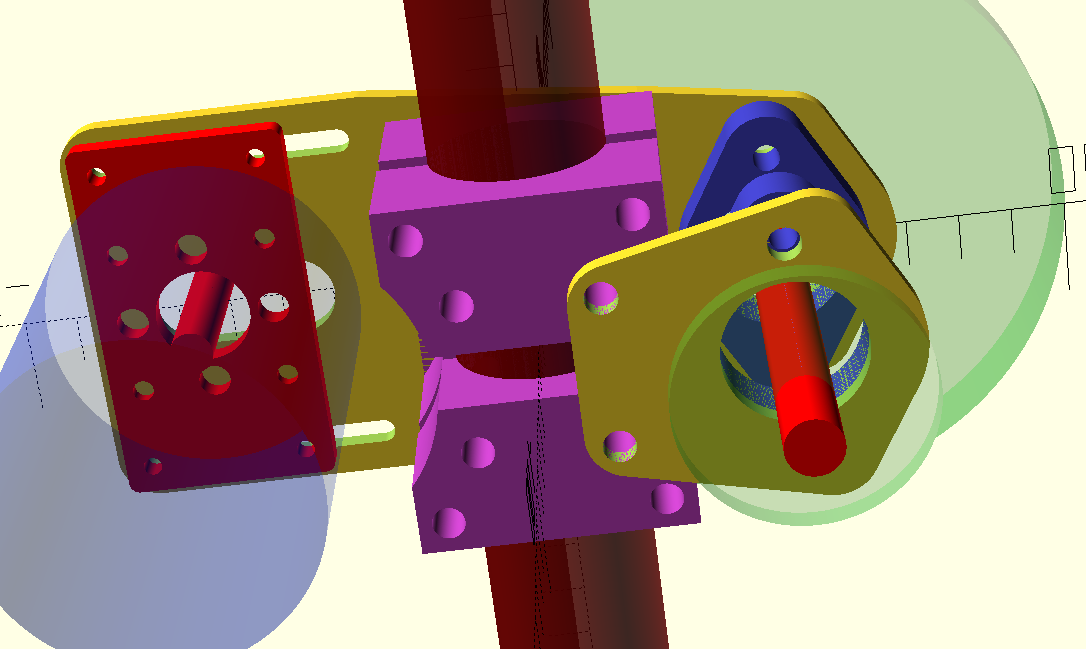
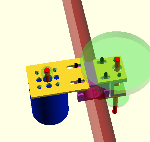
In this image here you can see the motor with it's shaft position in the mount, and the pulleys which are a bit transparent.
I tried to make multiple parts to keep cost down, the yellow plates could be laser cut, leaving only the tube mounts and trough shaft mount to be CNC'd, plus it leaves more adjustability.

pNDzUyp.png


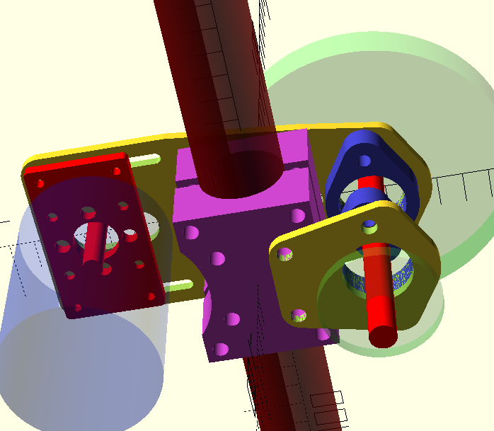
This is a more side view of the assembly. I'm not sure about the 'screw pattern'(?) I want to use. On the left side of the frame tube I want to make the top frame mount holes without thread and only the bottom pink frame tube mount have threads. On the right side of the tube I will then mount both sides of the trough shaft plates on the tube mounts, leaving only the left side of the tube mounts to 'pivot/bend' to create a pressure fit on the frame. I'm not sure about this, what do you think of this?

Another idea I'm now thinking about is to make the trough shaft mount one piece, including the tube mount, moving the 'slot' between the two frame mounts to the (in this image) top and bottom of the frame tube, and fingle something out with the motor mount. This would mean I have less adjustability on the troughshaft though. Currently I have to adjust 4 screws for a single axis of adjustment though, and I'd like to add an idler pulley to the motor drive side, and I have no idea where to put it right now.

rgpNoAR.png


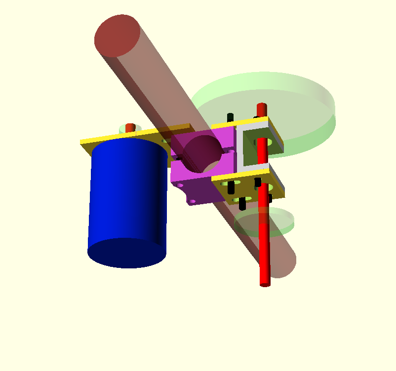
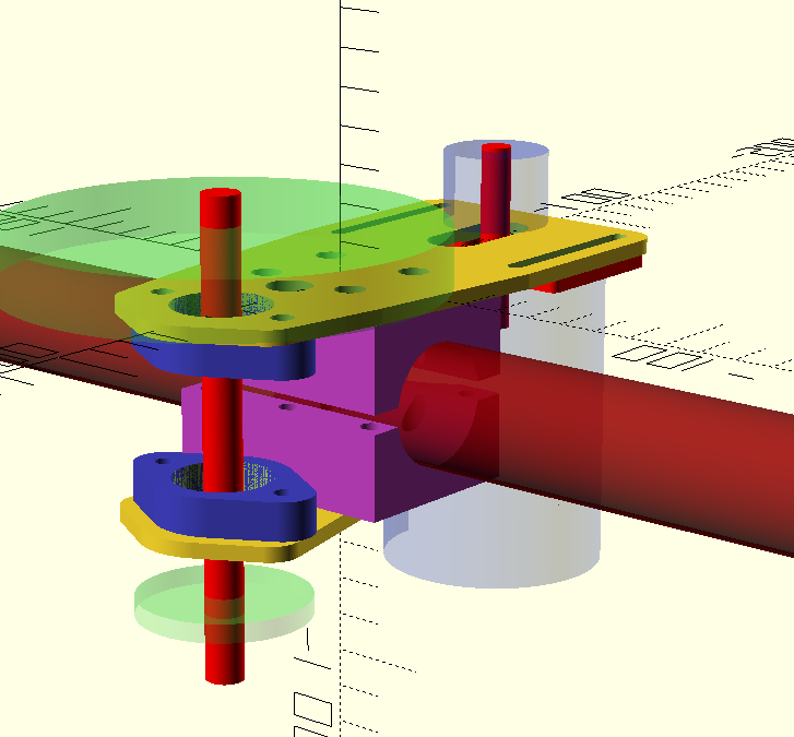
Here's another pic of the underside of the mount.

To give some context on the bike I'm going to build and how much power I'd be putting out: I have a SK3 6374 168kv motor, a self made 18650 6s5p 22.2v 14.5Ah 3c pack and I'm trying to go for range more then speed. If the tests are fine I'll build another identical battery pack and put them in series.

Let me know what you think! I prefer honesty, so if it's crap, let me know ;)

(Tool I used is OpenSCAD, it let's you make 3D models with code it's pretty frigging awesome)
 
Here is something more simple ...
https://endless-sphere.com/forums/viewtopic.php?f=28&t=87390&p=1276322&hilit=Left+Side+Mid+Drive#p1276322

but I would do it a little different,

With your set up , just use a crank set with 2 chainrings on the left side . ( you do have the old fashioned square taper bottom bracket on your bike ? )

Use your RC motor , mounted to a custom , made by you mounting bracket then just run a chain down to the largest chainring on the left side crankset you put on, Remember
you can use a 50/52/53 tooth chainring, or even larger by buying a track chainring for the left side crank/chainring set. That way you will get a good reduction ratio, you will have to do the math to
find out exactly what reduction ratio, let us know when you do, as other people would also like make a simple mid-drive using a RC Motor.
then
From the smaller inner chainring on the left side crank arm / chainring set run the chain back to the left side hub/cog.
 
My issue with that solution is that, to my understanding, that means your pedals will always be turning when your motor is engaged, right? That sounds super annoying to me, also since my freewheel is mounted on the rear wheel it means I wouldn't be able to use (some) regen braking. Also, something I forgot to mention I'd like to be able to take it off a frame and put it on another one without too much adjustment to the frame/bike. I have to swap the rear sprocket already but don't want to do much more to it, for this solution I'd have to replace the crank set (or perhaps make an adapter). I'd need the reduction drive regardless because of my motor spec I reckon

let us know when you do, as other people would also like make a simple mid-drive using a RC Motor.

Let me put down the math I've done so far, it's going to be in metric for a part because that's what I'm used to:
The rims on my bike are 28", the circumference of the tires is 2.15 meter, a comfortable pace on my bike is about 35KM/h that's:
35000 (meters) / 2.15 = 16279 R per Hour = 16279 / 60 = 271 RPM - this will be our reference number for our reduction drive, we want to come out more then this so we have some play room.

I bought a 168kv motor, meaning if you apply 1 Volt to an unloaded motor, it turns 168 times. My pack when it's fully charged will put out 25.2V, but will drop when putting under stress so I'll use 22.2V to calculate with, 3.7V per cell, this comes out at 3729 RPM.
My main belt reduction will be a 15 tooth gear on the engine and a 72 tooth gear on the trough shaft (with a 15mm 5m HTD) belt, which will give me a 4.8:1 ratio on the reduction drive. This means that at 3729 motor RPM, the trough shaft will go 3729/4.8 = 777 RPM
From the 777RPM on the trough shaft I will mount a 32 tooth rear chain sprocket on the rear wheel hub, and at a maximum a 11 tooth chain sprocket on the trough shaft, giving me another 2.9 ratio there, leaving me with 777/2.9 = 268 RPM on the rear wheel, which is about 34KM/h. This is of course all assuming I have 100% efficiency and will be cycling in a vacuum. I won't, sadly :lol:
From the cassette I will be taking the gearwheels for this project I also have 12,14,16,18,21,26 tooth sprockets, so I can swap out the trough shaft sprockets with bigger sizes to get a higher top speed (which I'll probably do, the ratio at 16:32 (2:1) tooth sprockets seems better)
Would a small web tool be usefull for this stuff? I could knock one out pretty easily
 
If your flipflop hub has a freewheel on the left side, rather than a sprocket bolted directly to the hub, it's going to prevent motor power from reaching the wheel, as it will be spinning the wrong way.

If there is no freewheel, but the sprocket is threaded on rather than bolted, then you will unscrew the sprocket while applying motor power. This you can fix by cutting a keyway into the thread/body of each, and securing a key in it.
 
amberwolf said:
If your flipflop hub has a freewheel on the left side, rather than a sprocket bolted directly to the hub, it's going to prevent motor power from reaching the wheel, as it will be spinning the wrong way.

If there is no freewheel, but the sprocket is threaded on rather than bolted, then you will unscrew the sprocket while applying motor power. This you can fix by cutting a keyway into the thread/body of each, and securing a key in it.

The commonest type of two-side hub these days is the fixed/free hub as used on fixed gear bikes. One side has a normal RH freewheel thread 10mm deep, and the other has a stepped thread for a RH fixed cog and its LH threaded lock ring. This fixed side, if used with a lock ring, would be acceptable for left side drive.

RH/LH fixed gear threading works very well, because as soon as the sprocket begins to unscrew, the lock ring tightens against it and jams. One drawback is that the sprocket thread is only half as deep as a normal freewheel thread and is more vulnerable to stripping. So it might not be a good choice for a motor drive that puts superhuman amounts of torque to the wheel.

Best, of course, is to use a hub with RH thread on the right and LH thread on the left, as was common about twenty years ago for BMX freestyle bikes (so adolescents who wanted to grind other people's property with the right sides of their bikes could use a left side chain). Unfortunately, most such hubs went out of production a long time ago. Old stock BMX hubs and Currie/USPD hubs threaded the same way are still in circulation to some extent, though.
 
amberwolf said:
If there is no freewheel, but the sprocket is threaded on rather than bolted, then you will unscrew the sprocket while applying motor power. This you can fix by cutting a keyway into the thread/body of each, and securing a key in it.

!!!! I hand't thought at all about this. I will pay attention to this when I take off the rear LH sprocket. Here's 2 pics of the rear sprocket http://i.imgur.com/8mRJx53.jpg http://i.imgur.com/6zRH6qB.jpg
Also made me realise I need to make a spacer or offset of some sorts for the new sprocket, or get lucky with the chain clearance.

@Chalo I added some pics, are you able to identify it from these? I can't determine the thread direction from here, though since this is intended to be flipped to be used as a fixie I imagine that it's 'the wrong way around'
 
I am still trying to figure out mid-drive systems and how to make them more simple,

So since I did not elaborate , here is my thinking,

You know how many / most if not all , of the mid drives have a freewheel build into/ designed into the right side/ normal drive side ... crank ?

Well instead of that , why not use a freewheel or clutch on the sprocket/cog that is connected to the shaft of the motor ?

That way when the motor is off or throttle not engaged , you can pedal as normal ?

For Example:

With my rear hub motors, since they are geared, I can , and often do on my small Q100c motor on a Road Bike, ... Pedal the Bike as normal with the motor / throttle not engaged .
then when I want more speed, etc. I just use the throttle, the electric system is still on the entire time, I am just not applying any throttle, so my bike rides just like a regular pedal bike.


eTim said:
My issue with that solution is that, to my understanding, that means your pedals will always be turning when your motor is engaged, right? That sounds super annoying to me, also since my freewheel is mounted on the rear wheel it means I wouldn't be able to use (some) regen braking. Also, something I forgot to mention I'd like to be able to take it off a frame and put it on another one without too much adjustment to the frame/bike. I have to swap the rear sprocket already but don't want to do much more to it, for this solution I'd have to replace the crank set (or perhaps make an adapter). I'd need the reduction drive regardless because of my motor spec I reckon
 
Your picture shows a fixed gear with lockring. The most elegant way to mount a big sprocket on that would be to machine a 1.37" x 24tpi LH thread into a suitably thick BMX chainring spider (about 6mm is ideal). Then you can use the lock ring you already have, and everything is tidy.

s-l300.jpg
 
I will elaborate a little more.

Many people say, and I agree, that it is best ... Not to use your 11 tooth cog on the rear cassette ?
that is it is better to use the 12 tooth, or even better yet 13 tooth cog to cut down on wear and tear on the bicycle chain.

I am seeing small tooth count sprockets on the motor shaft, either a cyclone or RC motor, small enough that when looking at the pictures , I wonder how you can make a freewheel or clutch small enough to be part of that sprocket on the Motor Shaft ? ?
 
Oh, I see your post on May 10th 2012 , you say the best way to implement what I am trying to say , is to do the motor shaft/ jackshaft, RC drive on the same side as the Drive Side, the right side,
in order to be able to run the motor with out the pedals/cranks / your legs moving .

Well don't you still need a freewheel in the cranks to be able to run the motor, to the back wheel, without using your legs/pedaling ?

I am trying to eliminate the need for freewheel in the cranks, since no one has yet made a bolt on freewheel to work with the newer BB30 Cranks / FSA 30 mm spindle , 2 piece Cranks, and Shimano Hollowtec II ( 24 mm spindle ) 2 piece cranks.

How's does one have a RC Mid-Drive and be able to run the motor ... without moving your legs/cranks , without having a freewheel in the crank itself ?

Would a freewheel/clutch on the RC motor shaft , only give you the ability to pedal without having the motor turn, or do RC motors have no cogging resistance like DD hub motors do ?


( until someone designs and makes a freewheel that bolts onto the BCD pattern on the Modern 2 piece crank sets , ( BB30/ Any Press Fit BB, and Shimano Hollowtec II ) ) .

Or ... who can design make an affordable freewheel for modern 2 piece crank sets ? ( white industry has great looking bling, but their pricing would put many/ most of us looking for another option )


spinningmagnets said:
You might draw some inspiration from these threads

"RC reduction simplified"
https://endless-sphere.com/forums/viewtopic.php?f=28&t=38213

"PaulD's Old Race Bike"
https://endless-sphere.com/forums/viewtopic.php?f=28&t=37729
 
ScooterMan101 said:
Oh, I see your post on May 10th 2012 , you say the best way to implement what I am trying to say , is to do the motor shaft/ jackshaft, RC drive on the same side as the Drive Side, the right side,
in order to be able to run the motor with out the pedals/cranks / your legs moving .

Well don't you still need a freewheel in the cranks to be able to run the motor, to the back wheel, without using your legs/pedaling ?

I am trying to eliminate the need for freewheel in the cranks, since no one has yet made a bolt on freewheel to work with the newer BB30 Cranks / FSA Cranks, and Shimano Hollowtec II cranks.

Yes :) I want to keep the ordinary peddle drive system in tact. What spinningmagnets shows is indeed what I want to build.
In my case the freewheel is on the rear wheel, not on the crank, I think. And I'm going to see if I can not implement any freewheels on the electric drive system, the motor controller (VESC) I'm going to use has regenerative braking, and in a way that means I can produce energy with muscle power if my batteries go flat. It's not like I'll have a lot of down hill on my route...since I live in the flattest country on earth :mrgreen:
What 99% likely will happen is that somewhere in the future I'll implement some sort of a clutch some where since regen braking is useless/not worth it. But the thought of it just seems so cool :D

Chalo said:
Your picture shows a fixed gear with lockring. The most elegant way to mount a big sprocket on that would be to machine a 1.37" x 24tpi LH thread into a suitably thick BMX chainring spider (about 6mm is ideal). Then you can use the lock ring you already have, and everything is tidy.

s-l300.jpg

Yes, I get your idea now, that is totally feasible, thanks!

spinningmagnets said:
You might draw some inspiration from these threads

"RC reduction simplified"
https://endless-sphere.com/forums/viewtopic.php?f=28&t=38213

"PaulD's Old Race Bike"
https://endless-sphere.com/forums/viewtopic.php?f=28&t=37729

Thanks so much! I've been browsing these forums a lot the last few weeks and time on time again I see you post stuff that helps a lot, thanks so much :) I also found this useful: http://www.recumbents.com/wisil/shumaker/default.htm
I've found a lot of inspiration in these forums, don't be surprised if I make a gear box at some point ;)

Thud's mounting solution really is a lot simpler, but lacks the adjustability I'd like, I'll go make a v2.0. Also from PaulD's build, I hand't thought at putting a bearing in the motor mount at all, that's a good one. I'll see if I can get away with that with the pulley width.

I'm wondering, do you guys think it's a good to use some 1mm thick rubber or something like that between the frame mount and the frame to add some dampening? (Motor vibration to frame/sound etc)
 
Version 2.0 for now:
MflNBdT.png

zPuTj21.png


I took a lot of inspiration from thud and pauld's builds that got linked. I like the mounting system a lot better now, each part has it's own screws to tighten it. Gonna see if I can figure something out for a pulley, because at my ratio (15:72) that undoubtedly will be a problem at some point
 
Yes, it's​ a good idea to limit your use of the 11 tooth sprocket on a cassette, to reduce wear and friction. But that's a cassette sprocket, which has short and narrow teeth to promote smooth shifting, on a pedal drive, which sees high intermittent torque peaks.

A motor sprocket usually has teeth that are full height and full width, so wear is less of an issue. The motor delivers torque more steadily, too. The one unavoidable drawback is that small sprockets mesh rather roughly and noisily compared to larger sprockets, with vibration becoming noticeable below 16t and increasing substantially with each increment smaller.

The moral of the story is that for a motor drive, it's a good idea to use sprockets with as many teeth as you can, but there's no compelling reason to avoid 11t motor sprockets if they buy you a more favorable reduction ratio or better physical packaging compared to a larger sprocket.

If you need a freewheel on the motor side of the rear wheel, then you'll need a right hand/left hand threaded hub to allow you to mount one on each side, with both freewheels operating in the correct direction. I have gotten sealed bearing BMX hubs like this in the past, and machined custom axles for non-BMX applications. This is a Specialized Flipside hub with the original axle extracted and replaced with a high strength aluminum axle that's 19mm on the right (to work with multi-speed freewheels) and fitted with a 25mm collar on the left, where only a left hand threaded single freewheel or a custom sprocket would be mounted. The axle ends are drilled and tapped for 8mm bolts to mount the wheel to the bike.
IMG_20170422_190826.jpg
 
I'd recommend that you slot the motor-mounting holes for the primary reduction tensioning. That way, the two in-line plates on that side can be made from a single longer rectangular plate. Just a thought...
 
eTim said:
And I'm going to see if I can not implement any freewheels on the electric drive system, the motor controller (VESC) I'm going to use has regenerative braking, and in a way that means I can produce energy with muscle power if my batteries go flat.
With the low efficiency of conversion of pedal power to electric, you are much better off with the freewheel in the system (or a clutch, or a controller that won't force regen when not using the motor) so it is still a normal pedal bike.

Otherwise you'll be pedalling hard enough to have ridden 2 or 3 times (or more) the distance you actually get while doing the recharging by pedalling. Then probably the power you get out of that won't go that 2-3x distance, it'll only go at best the amount you pedalled already (assuming the same speed, terrain, weather, etc).


If you were using the system for regen braking, that'd be a different thing, but if it's going to be used for pedal generation it's just not efficient enough to be worth it vs just pedalling alone.

Easier to carry a charger with you (and less time and effort).
 
Chalo said:
Yes, it's​ a good idea to limit your use of the 11 tooth sprocket on a cassette, to reduce wear and friction. But that's a cassette sprocket, which has short and narrow teeth to promote smooth shifting, on a pedal drive, which sees high intermittent torque peaks.

A motor sprocket usually has teeth that are full height and full width, so wear is less of an issue. The motor delivers torque more steadily, too. The one unavoidable drawback is that small sprockets mesh rather roughly and noisily compared to larger sprockets, with vibration becoming noticeable below 16t and increasing substantially with each increment smaller.

The moral of the story is that for a motor drive, it's a good idea to use sprockets with as many teeth as you can, but there's no compelling reason to avoid 11t motor sprockets if they buy you a more favorable reduction ratio or better physical packaging compared to a larger sprocket.

If you need a freewheel on the motor side of the rear wheel, then you'll need a right hand/left hand threaded hub to allow you to mount one on each side, with both freewheels operating in the correct direction. I have gotten sealed bearing BMX hubs like this in the past, and machined custom axles for non-BMX applications. This is a Specialized Flipside hub with the original axle extracted and replaced with a high strength aluminum axle that's 19mm on the right (to work with multi-speed freewheels) and fitted with a 25mm collar on the left, where only a left hand threaded single freewheel or a custom sprocket would be mounted. The axle ends are drilled and tapped for 8mm bolts to mount the wheel to the bike.

Sorry if I haven't been clear, my idea was to use a 15mm belt drive from the motor to the trough shaft, for the reduction drive. I have been reading other people's build threads and they indeed mentioned that high spinning, small, gears are noisy. I see I actually made a small error in my opening post, the setup I'm planning to make is 15:72 tooth, 1:4.8. This means at that 3729 motor RPM I used to calculate before the chain sprocket on the LH side of the trough shaft & bike will go at 777 rpm, still fast but not as bad as 3700 :)

Following the sdp-si center distance designer https://sdp-si.com/eStore/CenterDistanceDesigner I will only have 5 teeth in mesh on the belt, so I'll probably have to get an idler worked in there somehow: http://i.imgur.com/FHZi1zS.png I'd like to make something like this, get 2 straight belts on the motor driven pulley: http://www.pfeiferindustries.com/images/articles/Force_Deflection.jpg

spinningmagnets said:
I'd recommend that you slot the motor-mounting holes for the primary reduction tensioning. That way, the two in-line plates on that side can be made from a single longer rectangular plate. Just a thought...


Good thought, made me realise there is not much stopping it from making a V shape currently, would be a pain to tension

amberwolf said:
With the low efficiency of conversion of pedal power to electric, you are much better off with the freewheel in the system (or a clutch, or a controller that won't force regen when not using the motor) so it is still a normal pedal bike.

Otherwise you'll be pedalling hard enough to have ridden 2 or 3 times (or more) the distance you actually get while doing the recharging by pedalling. Then probably the power you get out of that won't go that 2-3x distance, it'll only go at best the amount you pedalled already (assuming the same speed, terrain, weather, etc).

If you were using the system for regen braking, that'd be a different thing, but if it's going to be used for pedal generation it's just not efficient enough to be worth it vs just pedalling alone.

Easier to carry a charger with you (and less time and effort).

I'm realising more and more that it's silly, trust me :D I did want to make it so I can easily disconnect the drive system on the side of the road when the battery is flat, and I will always bring the charger with me. I could also disable the regen in the controller if I want to, I'd have to figure out a simple way of doing that on the go (without a computer) though. I'm already planning on connecting a raspberry pi to the vesc with a wifi hotspot which my phone can connect to so I can monitor things. I'd be great if I can toggle and adjust things too, but I'm not sure how hard that would be at this point. I think it comes in the mail next week
 
Most likely simply disconnecting the battery from the controller would prevent the problem, as long as the voltage generated by the motor is not higher than the controller components can handle.

If you have no downhills to coast at high speeds, then it's unlikely to be an issue.
 
Made some more changes to my mount, at this point really have to start looking at manufacturing places. If I mange to find a CNC place for a decent price, I can change the design a bit and move the bearing housings of the trough shaft inside the frame mount I reckon, this would give me a lot more then the current 15mm of adjustability on the motor side and perhaps give me room for a idler pulley.

mnQzBVR.png

Ebr5T5v.png

qRuPuHQ.png


Another idea:
I9FsNCk.png


This would work right? This would allow me to have everything cut with a water jet

Also, bit unrelated to this specific thread, but I still haven't received my VESC, or any replies to my now 2 e-mails about order updates...it's been 2 weeks now :/ I ordered at vesc.co.uk in hopes to get it quick because that's what they advertise with but alas... Hope I don't have to cancel and re-order
 
I've never seen a deep waterjet cut that's true and straight enough to use it for tubing blocks. I expect that feature would need to be cut with a mill or the like.
 
Found a way better solution for the bearings: https://nl.aliexpress.com/item/1Pcs-Pillow-Block-Bore-KP000-10mm-Inner-Diameter-Zinc-Alloy-Metal-Ball-Bearing/32648370300.html
HI0Z540.png

I'll just mount these to the side of the frame mount, it would fit I reckon. Gonna mock something up now.

@amberwolf, I'm not sure how ideal shipping those parts overseas would be

@Chaio, good one. Maybe I can do the frame blocks myself, with a minimal investment in a cheap drill press and a xy vice and some cutting bits. I'd love to get into that stuff anyway. Then I'd only have to let the 2 motor plates and perhaps an idler plate get cut

@Lebowski, hahaha ja! Bijna dan ;)

v3e9Zgg.png


What do you reckon? Still got to rework the bolt holes now, but looks good to me so far. Also gives 1.5mm more playroom at the motor side
 
I would suggest not trusting two halves of your frame clamp to line up perfectly and give you a nice aligned shaft. Just attach your bearing/motor mounting plate to one of the clamps and the other side just holds it to the frame.
 
I think it will work well-enough for a V1. It may end up working very good, but it will take a few months of road-testing to truly satisfy that question. Well done!
 
Back
Top