Did I fry my Baserunner?

nickceouk

10 W
Joined
Jan 18, 2020
Messages
86
What could happen if I wired the polarity of the battery to the Baserunner controller wrong?

I was transitioning from test wiring to properly terminated connectors today and unfortunately made a big mistake.
When I connected and switched on the "magic smoke" came out and I switched off immediately.
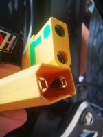
I later looked at the wiring and the smell of something burnt was on the antispark xt90 connector.
Rewired everything properly and the controller seems to work.

What makes me suspicious that there might have been damage to BR is that the output when I throttle down the road is very jerky.
I then pressed the bike down standing next to it while applying the throttle and was able to stop the wheel from rotating. Weak throttle as I was expecting a 750w geared hub motor to be able pull the bike from under me in this test.

I know one of the key differences of BR compared to OEM Chinese controller is the torque vs speed based throttle. That's why I am unsure if the controller is damaged or if it's something to do with settings.

Is there a way to change from torque to speed because that's what I can compare with and know how the bike performed with OEM controller? Maybe some other settings or test?
 
Rewired everything properly and the controller seems to work.

BaseRunner by Grin put in protections for just your case scenerio, thats their market which would range from a first timer buying without worry about cost so not much time delay (ppl research for months sometimes, seems to be the norm in diy saving a buck) going for the best right away, to old timers using their BR and maybe saving for it.

That type of protection costs more, takes away profit which is why generics wouldnt do it.

To me its different then just putting in a passive safety device (fuse) to blow, and have to replace then to have it hooked up wrong, cook the connector but not hurt any electronics and have it still work, in your case you have some issues but it could have been worse. I'd look at the area around the connector for damaged components from the heat of the melt action for your other issues that you have currently.
 
Last edited:
BaseRunner by Grin put in protections for just your case scenerio, thats their market which would range from a first timer buying without worry about cost so not much time delay (ppl research for months sometimes, seems to be the norm in diy saving a buck) going for the best right away, to old timers using their BR and maybe saving for it.

That type of protection costs more, takes away profit which is why generics wouldnt do it.

To me its different then just putting in a passive safety device (fuse) to blow, and have to replace then to have it hooked up wrong, cook the connector but not hurt any electronics and have it still work, in your case you have some issues but it could have been worse. I'd look at the area around the connector for damaged components from the heat of the melt action for your other issues that you have currently.
Very well put on Grin components vs generic stuff. Glad the protection is there and I see no damage in cabling.

I am doing an upgrade thinking I would get a better ride. Those were the expectations but in reality if I could do something different I would probably get a flipsky 75100. They also have a Bluetooth module and much better connectivity.

I hate the CA3 interface, that's why I didn't bother getting one this time. I know it's somewhat shortsighted of me since in terms of it's features it's the best device and other devices can not match but the UI etc is a deal breaker. There is no reason for the display to be so backward and poor GUI.

Flipsky has a decent app and can be interfaced through an Arduino or perhaps esp32. That opens so many doors and I feel better about the ESC standards than ASI BAC Grin TRRS contraption on Windows or Android
 
If you got smoke, something is damaged in whatever produced the smoke, at minimum, and almost always in the electronics connected this way.

Connecting a battery backwards almost always damages or destroys various controller components, usually FETs (that drive the motor) and often the LVPS that makes the 5v / 12v / etc. There can't be any reverse protection built into the power section (if there was, regen couldn't work), though it's possible for a system to have LVPS reverse protection.

How severe the damage is is unknown, often impossible to know exactly without lab testing of each component (not worth it), but the damage is there.


I highly recommend NEVER using any form of connector that can be installed in more than one orientation--if it isn't keyed in a way that makes it impossible to connect wrong without doing abnormal things or using force you know is excessive, don't use it, especially on power connections.

And if it's a DIY connection / cable, ALWAYS verify polarity with a multimeter before actually connecting anything. (Even premade stuff can be wired wrong, of course, so always checking things the first time before connection is a good idea).
 
Regarding the CA... you can use it's features without using it's display. Just don't put it on your handlebars. If you really don't want the display at all you can take the CA main board out and install it inside your battery casing, etc., and then just use the serial connection from it to the computer for any setup operations. If you prefer a different GUI you can take the serial output from it and run that to whatever kind of dashboard you want to design / build (there are existing projects for this in various threads and websites).
 
Regarding the CA... you can use it's features without using it's display. Just don't put it on your handlebars. If you really don't want the display at all you can take the CA main board out and install it inside your battery casing, etc., and then just use the serial connection from it to the computer for any setup operations. If you prefer a different GUI you can take the serial output from it and run that to whatever kind of dashboard you want to design / build (there are existing projects for this in various threads and websites).

I still can't believe that I managed to smoke the controller after all the work I put on this conversion! Smoke means damage and doubt in the back of my head ...new controller.

It's reassuring to know that CA3 is capable of being used with custom display through serial and it's baffling that no one ever made such a display. Probably people expect CA to have done it themselves already ...
I watched a video last night of Justin giving a fantastic lecture on regen braking.

I still like Grin a lot but I need to evaluate buying a flipsky 75100 with Bluetooth dongle and esp32 DIY display(I wanted to arrive at custom display anyway) Vs Baserunner+ CA3.
Pricewise there is no contest.

Off-topic

Throughout the conversion I also started noticing other stuff that annoyed me - the ebike has a massive frame and yet all cabling is externally routed which is very annoying. The cables themselves are unnecessarily routed individually to the handlebar instead of one cable that splits at the handlebars or how about routes through the handlebar to wherever the component is. No cables exposed, protected from damage and also not getting tangled or minding cabling while moving around the bike.

Might sound like a minor thing to get so fixated on but it irritates me.

I also want to conveniently shuffle between batteries and the issue I had there is doing the switching while staying on the bike and or pooling the batteries for one big power source.

I can't believe that I have to switch xt90 or similar connector each time manually and have an evolved controller in the bike doing precisely timed phase pulses like it's nothing at the same time. It's just not making any sense.

That's where the ... "Battery blender" Datex2 for 3 batteries came into question. Someone noted that it's possible to do what Datex sell with high voltage single phase rectifier bridge Hooked to each external battery output. There is also an eBay sold "battery blender" for two batteries and significantly cheaper.

Also the flipsky anti spark switch (one switch per battery) which may allow me to use each battery one after the other if I make sure to switch off before switching on the next one(could automate that too hopefully and avoid possibility of 2 or more batteries being on at the same time)

The reason why this stuff is important to me is not just connvinience ... there was an article on an ebike that was taken off a train and refused onboard because of how "ghetto" the wiring and everything else looked.
They probably had a valid point on that build but I want to make mine look as OEM factory built as possible and avoid this sort of situation. That's why I leaned towards a foldable design for the ebike frame as legally they are allowed on a train. That opens a lot of possibilities in principle although train rides here in UK are crazy expensive and make no sense. At least I could keep the possibility open of pushing the bike into the nearest train station if I get a technical issue somewhere far from home.

I also have some carbon fiber rolls and vaccum bagging equipment with supplies. After trials and errors and frustrations or revelations keep mounting I would have liked to be able to just design whatever makes sense. So far I have come to a conclusion that a bike with builtin battery towing a trailer with several batteries would work better than a big size cargo bike. I can essentially tow everything using trailer batteries then set camp and go for a spin with just the bike to check what the surrounding area is like locally.

There is a video from easy composites where they show how a carbon fiber bike frame is made.
There is also the vegoilguy on YouTube where a decent method to cast metal items from 3d prints is shown(not Sand casting). He is using resin 3d printer with crazy accuracy and a porous plaster with vaccum pulling machine. The results are exceptional precision from what is shown and it's not cheap but also not crazy break the bank prices to arrive at a similar setup.

I probably need to open a ebike build post yet I keep postponing everything until I get a 3d printer(fdm & resin) , vaccum casting gear (3 in 1 - vaccum porus plaster before moulding, electric furnace and vaccum casting 2L Vacuum Investing Casting Machine Jewelry Waxing Combination Making Tools | eBay ). Adding a Laser cutter to wishlist (diode powered 40W) making it possible to make whatever makes sense and then adapting, iterating ideas.

Dreaming on for the moment...will be glad to have the bike working and I am leaning towards flipsky vesc 75100 with Bluetooth .Throttle, ebrake plus android app to toggle the settings. Retro fitting a torque sensor is interesting...back to dreaming again :)
 
Last edited:
On topic
This is where the smell of something burning comes through. The female connector has a strong smell and black residue on one of the pins. The connectors were joined outside the frame and that's where the magic smoke appeared. The controller from inside the E-bike frame "smells fine" as in no burned out smell detected there😂.

Going back to OEM electricals for now(with my tail between my legs figuratively speaking)and waiting on Grin to confirm if BR has reverse polarity protection

OEM controller works as previously but what surprised me is that even though I was able to tow a 30-40kg trailer with this bike ....yet when I press on the seat with max throttle and hold the bike I can stop the wheel from spinning. That's really strange as I expected much stronger torque on a 750w motor.
It zips greas with Chinese OEM controller that's configured for speed(not torque) but it has really weak torque once push comes to shove.
 

Attachments

  • IMG_20231007_143704.jpg
    IMG_20231007_143704.jpg
    3.4 MB · Views: 2
Last edited:
THe damage on that connector is arc damage.

that kind of damage only happens when a connection has a gap in it that the arc has to cross (regardless of polarity).

If the damage matches that on the precharge ring and main connection barrel of the mating connector and the spacing between them, then the arc was actually between those, and not between the two connector halves. (it would be pretty wierd for it to be between the precharge and main, as the only way that could happen is if they were different polarities, and I don't think you can wire these connectors that way)

Otherwise there is a problem with the connectors themselves not mating correctly leaving a space around the pin to the barrel (airgap) everywhere, or that the connector halves weren't actually plugged into each other, so that the voltage had to arc across the connector barrel to the mating pin.
 
It's reassuring to know that CA3 is capable of being used with custom display through serial and it's baffling that no one ever made such a display.
They have; I already said this; you can search for the threads and websites about them.


the ebike has a massive frame and yet all cabling is externally routed which is very annoying. The cables themselves are unnecessarily routed individually to the handlebar instead of one cable that splits at the handlebars or how about routes through the handlebar to wherever the component is.
Drilling holes in the frame to route wires thru compromises the frame itself, unless you also install tubes brazed or welded to the frame to pass the stresses thru the walls. (even then, it complicates the structure, and changes the way the stresses pass around things, so it doens't see the stresses the way it was designed to...holes for rivnuts, bolts, etc all do the same thing, but those should be part of the design consideration when making the frame in the first place and not be as likley to cause structural issues if it's all designed right).

A hole in the wrong place where stress is concentrated will eventually break the tubing there, and could cause a serious problem for the rider if it happens while in motion.

SB Cruiser used to have cables routed thru the tiller, until one day as I pulled up to my gate at the house the handlebars and tiller came off in my hands, broken at the point the hole for that was. Someday I'd like to retry the routing, but only with a design that uses a separate nonstructral tube to contain the wiring, or similar, so there's no holes in the structural parts.


I also want to conveniently shuffle between batteries and the issue I had there is doing the switching while staying on the bike and or pooling the batteries for one big power source.

I can't believe that I have to switch xt90 or similar connector each time manually and have an evolved controller in the bike doing precisely timed phase pulses like it's nothing at the same time. It's just not making any sense.
There are plenty of ways to combine or switch batteries safely, there are MANY threads about this over the years with extensive discussion if you are willing to research them.


That's where the ... "Battery blender" Datex2 for 3 batteries came into question. Someone noted that it's possible to do what Datex sell with high voltage single phase rectifier bridge Hooked to each external battery output. There is also an eBay sold "battery blender" for two batteries and significantly cheaper.
Just a note because these come up often, and there are considerations that can destroy a system:

Any blender that uses diodes between battery and controller, *or* can switch batteries off disconnecting them from the controller) will prevent regen current from reaching the batteries.

If you need regen you can't use them.

If your system is regen-capable (even if it is not enabled) because of a clutchless geared motor or direct drive motor or any middrive without a freewheel/clutch between it and the wheel, and voltage generation occurs for any reason that exceeds the voltage capability of any part of the system on the controller side of the blender, those parts will be damaged or fail. That can include but isn't limited to:
--controller FETs
--controller LVPS (and anything connected to that if it fails the wrong way, such as throttle, motor halls, PAS, etc)
--DC-DC for lights/etc
--battery-voltage-level lighting

The "smart" ones are worse than the dumb diode ones because you don't (can't) know how they were programmed / designed to react to all the possible conditions, so you can't predict how your system will behave in any particular situation until you have experienced it enough times to get the patterns down. :( (and potentially have had to replace hardware due to failures caused by this unpredictability).
 
I don't understand. Does the bike still work at all? If so maybe it's best to try to troubleshoot what would make it run better first.

If you can't do a Grin product instal, you might have more trouble with a China one that will require soldering also.
The bike works and I couldn't notice a difference in its performance after putting back the Chinese original controller and components (display, lights etc).

I am waiting on Grin to confirm if the BR has reverse polarity protection but even if it does something was not working well in terms of the motor output on the road.
BR outputs torque which is different than Chinese voltage(RPM) from what I learned but I struggled to verify better torque or RPM yesterday. It would cutoff at certain point the throttle them on again and it wasn't pleasent or predictable.
I suspect that either the battery was cutting off the BR possibly due to it exceeding current draw or this is how BR works after hitting a torque level and backing off(it was on a flat road).
I since watched Justin converting a Radrover with Frankenrunner and that confirmed to me that it's not how other grin controllers should perform.

P.S. never had an issue with Soldering only limited by my skills. Then again jst 2.54mm connectors can be crimped (best to solder after crimp imo) and make my own Juliet, higo, xt90, Anderson, mt60 ... I get huge satisfaction when things are well thought out, make sense and quality made. Having suitable 3d printer / home metal castings option which is also a thing there is whole new level to lookup up to and explore now.

In fact I anticipate that going forward it's a standard situation to not know how a certain OEM system operates so think a ready spliced jst connectors, software controlled breadboard (if it exists) , logic analyzers should be made trivial as an aspiration.

Watched Justin splicing a cable and replace a hall sensor and am convinced I am not perfect but also ok and could possibly add improvements to many workflows and usability solutions.
I am off topic again.
 
Last edited:
They have; I already said this; you can search for the threads and websites about them.


Drilling holes in the frame to route wires thru compromises the frame itself, unless you also install tubes brazed or welded to the frame to pass the stresses thru the walls. (even then, it complicates the structure, and changes the way the stresses pass around things, so it doens't see the stresses the way it was designed to...holes for rivnuts, bolts, etc all do the same thing, but those should be part of the design consideration when making the frame in the first place and not be as likley to cause structural issues if it's all designed right).

A hole in the wrong place where stress is concentrated will eventually break the tubing there, and could cause a serious problem for the rider if it happens while in motion.

SB Cruiser used to have cables routed thru the tiller, until one day as I pulled up to my gate at the house the handlebars and tiller came off in my hands, broken at the point the hole for that was. Someday I'd like to retry the routing, but only with a design that uses a separate nonstructral tube to contain the wiring, or similar, so there's no holes in the structural parts.


There are plenty of ways to combine or switch batteries safely, there are MANY threads about this over the years with extensive discussion if you are willing to research them.


Just a note because these come up often, and there are considerations that can destroy a system:

Any blender that uses diodes between battery and controller, *or* can switch batteries off disconnecting them from the controller) will prevent regen current from reaching the batteries.

If you need regen you can't use them.

If your system is regen-capable (even if it is not enabled) because of a clutchless geared motor or direct drive motor or any middrive without a freewheel/clutch between it and the wheel, and voltage generation occurs for any reason that exceeds the voltage capability of any part of the system on the controller side of the blender, those parts will be damaged or fail. That can include but isn't limited to:
--controller FETs
--controller LVPS (and anything connected to that if it fails the wrong way, such as throttle, motor halls, PAS, etc)
--DC-DC for lights/etc
--battery-voltage-level lighting

The "smart" ones are worse than the dumb diode ones because you don't (can't) know how they were programmed / designed to react to all the possible conditions, so you can't predict how your system will behave in any particular situation until you have experienced it enough times to get the patterns down. :( (and potentially have had to replace hardware due to failures caused by this unpredictability).
Sorry AW, yes you did say it and yes there are displays for CA3.

I wouldn't want to drill, compromising the structural integrity and can appreciate when Justin did drill to install a torque sensor on the RadRover he mentioned this fair and square -" at your own risk and warranty voided".
Well, I am also way ahead of myself with so much ground and basic aspects not covered... If I do get round to it will probably be a discussion in the E-bike builds section.

Thank you, I really wasn't aware of the regen capability downside to "battery blenders".
The other option I was considering is flipsky Antispark switch which comes with low voltage toggle switch. Each battery with one such a switch wired to controller and a means to toggle between safeguarding against the possibility of two switches coming on at the same time.
Have you come across the same kind of regen limitation discussion on the flipsky anti spark switch(or similar principle devices). I have some research to do on the switches.

as always thank you for the shared wisdom @amberwolf !

P.S. I think it's possible to design the tube with internally different geometry and cast the design with lost resin/pla. I don't know why we keep making things with basic shapes when it's possible to custom form the whole "handlebar" ....I suspect there will be no added weakness depending on design.
The other option is similar to photo and it's something I have seen on a Xiaomi miija 360 scooter I had years ago.


Attachments

  • slot tube.jpg
    slot tube.jpg
    52.7 KB · Views: 1
Last edited:
I wouldn't want to drill, compromising the structural integrity and can appreciate when Justin did drill to install a torque sensor on the RadRover he mentioned this fair and square -" at your own risk and warranty voided".

Well, unless there are already holes / channels in the frame you have, you don't have any other options to run wires thru your frame except to drill new holes.

If you want to do it on a custom frame, then sure you can build it up to have internal routing options...but anything that "breaks" the wall of the structural tubing or changes it's shape from a plain tube (round or square) changes the way the stresses are passed from one part to another, so you have to either analyze the design with software that can model that stuff to be sure it's still strong enough for your specific needs, or build it and test it until it breaks so you know where the breaking point is, and be sure to stay below that limit. ;)

If it doesn't break or exhibit signs of eventual failure by some point well above your usage needs, then you could stop before that point and have a good chance of it lasting you just fine.

The testing can be done by just riding it like you would normally, or even harder, but there's always the risk that it will fail when you really really don't want it to, like in traffic. :(

I pretty much do all my testing the hard way, and fix the problems as they arise...but I try to think it all thru first and see if I can find examples on the internet of failures of structural methods / materials I am going to use, so I can avoid the obvious oopsies and save myself as much grief as possible. :oops:


I don't know how the shaped-channel tubing you've pictured would fare compared to standard-shaped round or square tubing under the same stresses; I've never had anything built from it that I could use to test that. I'm sure there is info online somewhere about it, though, if you poke around enough.


The other option I was considering is flipsky Antispark switch which comes with low voltage toggle switch. Each battery with one such a switch wired to controller and a means to toggle between safeguarding against the possibility of two switches coming on at the same time.
Have you come across the same kind of regen limitation discussion on the flipsky anti spark switch(or similar principle devices). I have some research to do on the switches.
I don't know how those work. But if they can isolate the battery from the system, then they too can cause the problem, if any conditions occur that turn them off then the regen/motor current has nowhere to go. (same with a BMS, see below)

I suspect they are just "ideal diodes" like the ones Tiberius, Fechter, Methods, etc., have threads for here on the forum, and if so then they do indeed disconnect the pack when they turn off.

You're much better off as far as this problem goes by simply directly paralleling the batteries, and just ensuring they are at the same voltage when you do so. They will then stay at the same voltage the entire time they are connected, and they will also see less load and be less stressed, as the load will be divided between them based on their own characteristics (internal resistance, etc).


BTW, it isn't *only* regen that is a problem--if the motor controller isn't already designed to handle the field collapse when it stops powering the motor, then the "flyback" current collapsing in the coils creates a voltage spike similar to regen--it's much much shorter, but if it's high enough voltage it can still do the same damage.

So...making sure at least one battery has a hard connection to the controller that can't be disconnected except by you might save the system from any of these (rare) eventualities.

It's still possible for it's BMS to turn off because of some exceeded limit, and you generally don't want to interfere with that, so this is still a potential issue but it is not typical that these problems occur from a BMS shutdown,. from the reports and troubleshooting threads seen so far. (it could, under the wrong conditions...but it would take careful user-management and thinking ahead on every ride and usage to prevent this sort of thing--the only other way would be to not have the BMS shut off the output, but instead to shutdown the controller, which would require modification of your battery / etc to do).
 
Grin support came back to me and unfortunately the Baserunner has no reverse polarity protection.
They were very nice and offered a discount if I decided to buy a replacement but that's unlikely as I am going to use the ebike with OEM controller instead.

I really appreciate all the support and input I got here on Endless sphere!
 
Back
Top