
electric_snowshoes
10 mW
- Joined
- Dec 19, 2011
- Messages
- 26
First off I'm on a borrowed computer so my response may not be punctual. Second issue is I need to learn photo transfer to ES Forum site. I have got the images from the SD camera card to a computer file.
Amberwolf has a topic for the same motor class but a different reason than mine. He has succeeded in placing hall sensors to bypass the manufacturers 2 sensor method & use an ebike controller instead of the factory controller & joystick. I have the matching controller but no joystick.
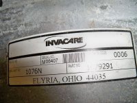
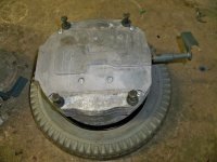
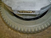
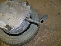
This is a different motor (L & R pair) than in Amberwolf's thread. Its a Invacare, part # 1079291 from Elyria, Ohio, date stamped Jan 03, 2003. We know these motors can run at low rpm without overheating.
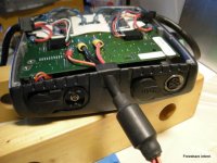
The Topic : Can the matching controller be utilized / converted to run a single motor of the pair, ebike style?
I'm aware there are various sensing methods in the controller, such as all wheelchair drive components must be attached & working. There is also limiters for speed & user reaction time usually programmed by the retailer staff to meet the need. Can these be removed or bypassed?
The missing joystick may or may not have an on/off switch & indicator / troubleshoot bar lights like Perry & Giles echairs & carts. The joystick function needs to be replaced as only forward & throttle functions are wanted.
Are there members interested in this? Is there members with the knowledge & time to guide a photo study of the motor & controller?
There may be useful info in robotics forums, please PM instead of posting off topic here. Lets see if solutions exist first. Thank you for considering this topic.
Amberwolf has a topic for the same motor class but a different reason than mine. He has succeeded in placing hall sensors to bypass the manufacturers 2 sensor method & use an ebike controller instead of the factory controller & joystick. I have the matching controller but no joystick.
This is a different motor (L & R pair) than in Amberwolf's thread. Its a Invacare, part # 1079291 from Elyria, Ohio, date stamped Jan 03, 2003. We know these motors can run at low rpm without overheating.
The Topic : Can the matching controller be utilized / converted to run a single motor of the pair, ebike style?
I'm aware there are various sensing methods in the controller, such as all wheelchair drive components must be attached & working. There is also limiters for speed & user reaction time usually programmed by the retailer staff to meet the need. Can these be removed or bypassed?
The missing joystick may or may not have an on/off switch & indicator / troubleshoot bar lights like Perry & Giles echairs & carts. The joystick function needs to be replaced as only forward & throttle functions are wanted.
Are there members interested in this? Is there members with the knowledge & time to guide a photo study of the motor & controller?
There may be useful info in robotics forums, please PM instead of posting off topic here. Lets see if solutions exist first. Thank you for considering this topic.


.jpg")