DIY Car Battery: how to limit the charging voltage?

Joined
Jan 29, 2016
Messages
1,146
Location
Shanghai
Hello guys,
My lead acid car battery has been showing signs of aging recently and it will probably be time to replace it within a few months.
Just to be clear, it's not an electric car, it's a petrol engine and I'm talking about the battery that helps with cranking and whatnot.

I'm toying with the idea of making my own battery, mostly for fun but also in order to get slightly better performance (my car is very, VERY sensitive to battery health and all sort of electrical gremlins tend to pop out when the battery is not in perfect health)

Anyway, I already know what cells I'd like to use, I'm already familiar with making DIY batteries, connecting and configuring the BMS and whatnot.
But for this particular project I'm unclear about the charging aspect.
A a car alternator can output a maximum of 14.7 to 15V, and I'm planning on using A123 pouch cells that should generally not been charged over 3.6V per cell (so with 4S that'll be 14.4V).

I'd like to avoid overcharging the cells for obvious reasons, so I'm wondering how I should do this.
The BMS can be set up to cut the charge at any voltage I want, but I don't think it would be good for the car if the BMS cuts off the battery while driving. So basically I think I need some kind of charging regulator between the alternator and the battery in order to lower the voltage to ideally a maximum of 3.5V per cell. so 14V (slightly undercharging in order to increase longevity).

Anyone here with some experience of building a car battery?
Suggestions are very welcome

Thanks!
 
I drive since 3 years with a Porsche 40Ah lifepo 12V battery which I bought used, around 2 years old.
The car is only used in the warmer period.
The battery is made of A123 cells and the integrated bms cuts over 14,6V. The alternator is a 1.4kW type and the car has no big electronic loads, as there exists no electronic stearing and none of the not nececary gadgets invented in the last 30years. The only thing consuming energy is the fuel pump and the engine electronics.

My biggest concern was the charging current which can go up to 90A, but only for a few minutes.
I have done a capacy test every year and the battery has still 38Ah until the BMS cuts off.
 
Do you have active regulation of the alternator? I mean if there is an external ecu that controls the alternator. That is usually the case with start/stop systems, and then there is usually a current/voltage sensor on the battery negative. Otherwise the alternators are usually fixed at 14,4V.
 
toying with the idea of making my own battery
This is a wonderful question. I am embarking on a similar project, through my chemistry is different, 6S LTO (Tosh. SCIB). One of my wonders is voltage spikes in a SLA designed system causing long-term problems with lithium chem. and BMS. Is this a concern and if so addressable?
 
Wanted to replace my SLA in my EV but at the time chickened out and got a Deep Cycle trolling motor battery. Don't need the cranking amps and it has been going for 5yrs now. No more Lead for me the Lipo's seem to hold up. Good luck will follow this project.
 
I drive since 3 years with a Porsche 40Ah lifepo 12V battery which I bought used, around 2 years old.
The car is only used in the warmer period.
The battery is made of A123 cells and the integrated bms cuts over 14,6V. The alternator is a 1.4kW type and the car has no big electronic loads, as there exists no electronic stearing and none of the not nececary gadgets invented in the last 30years. The only thing consuming energy is the fuel pump and the engine electronics.

My biggest concern was the charging current which can go up to 90A, but only for a few minutes.
I have done a capacy test every year and the battery has still 38Ah until the BMS cuts off.
Interesting, thanks!
So you mean there's no device limiting the voltage on the charging side? Only a BMS set up for a 14.6V limit?
What happens when the BMS cuts? Did it already happen to you during driving?

I wouldn't worry to much about the charging current, these A123 pouch cells can take a lot of abuse!
Thanks a lot for the return on experience. Do you happen to know what BMS was fitted inside your battery?


Do you have active regulation of the alternator? I mean if there is an external ecu that controls the alternator. That is usually the case with start/stop systems, and then there is usually a current/voltage sensor on the battery negative. Otherwise the alternators are usually fixed at 14,4V.
I'm not sure if there's any kind of active regulation, is there any way I can check? The car is a Maserati Quattroporte S
There's no start/stop system on it but the alternator isn't very accessible as it is right in the middle of the V8, under the intake, so it's not easy to check its reference.
 
I'm not sure if there's any kind of active regulation, is there any way I can check?
Just leave the headlights turned on for 5 minutes or so (engine off). then probe the cigarette lighter socket or fuse panel with volt meter, with engine running, and monitor the voltage. For amps, you'll need a clamp meter connected around the one of the battery cables. You can also check the vehicle's service manual for charging specs. Yes, nearly all vehicle charging systems have regulation, but usually need higher engine RPMs (and electrical load) to confirm max output.
 
Last edited:
Just leave the headlights turned on for 5 minutes or so (engine off). then probe the cigarette lighter socket or fuse panel with volt meter, with engine running, and monitor the voltage. For amps, you'll need a clamp meter connected around the one of the battery cables. You can also check the vehicle's service manual for charging specs. Yes, nearly all vehicle charging systems have regulation, but usually need higher engine RPMs (and electrical load) to confirm max output.
Thanks!
The problem I see on this method is the following:
Let's say that without the engine running the battery sits at 12.00 V
Then I switch the engine on and it starts charging, it will show 13.5V
This only tells me part of the story.

The reason is that this voltage will constantly change and slowly increase over time, because the more the battery charges the lower the current gets, so the current will tend to drop at the end of the charge cycle and the voltage will tend to keep rising.

I believe the real problem will arise on long travels, when the engine has been running for an hour or more and the battery is close to 100% SOC. At this point I wonder if its possible that the charging voltage will go over 14V. The A123s are most happy when they remain under 3.5V. On my bikes I've set the limit to 3.5V as there is no significant capacity gain going over this voltage and it's not really good for cell longevity anyway. So 14V would be the ideal maximum I'd like to set in the BMS, if possible.
In such a case, the BMS would cut and I don't think this would be good for the car if this happens while driving.
What I don't know is if this can ever happen in real life while driving, because there are always things that consume electricity while driving so it's possible that these loads prevent the battery to ever charge up to 100%.

However, I can see it happening while plugged on a battery tender, because it will charge up to 14.7V for sure. In this case it would also be a problem because the battery would disconnect temporarily and I would have to reset the clock of the car.

Maybe the best solution is to just not care about this issue and assume that the A123 will tolerate these slightly higher voltages, just like the experience of dominik h seem to prove. The absolute maximum voltage I've seen once the charge is completed using the battery tender is 14.7V, which would be 3.65V per cell.

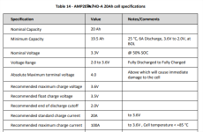
According to the spec sheet of these cells the absolute maximum is 4.0V per cell so I should be safe no matter what, but it would still be better to be able to limit the max voltage to the recommended level.

1749786636857.png

I think I might be overthinking/overcomplicating things, maybe I should just build the thing and see how it goes.

The reason why I'm considering this whole thing is that this car tends to eat batteries pretty quick and it gets all sorts of electical issues with the various computers and ECUs if the voltage gets low (which can happen especially when cranking). I've got exceptionally great experiences with A123 cells so I think they would be a great fit for this application as they can deliver loads of current and they tend to be bulletproof (the cells on my motorcycle were manufactured in 2012 and they still work fine despite a lot of abuse).
Just not willing to take too many uncalculated risks because any damage to the electrical systems of the car will be insanely expensive to fix.
 
The problem I see on this method is the following:
Let's say that without the engine running the battery sits at 12.00 V
Then I switch the engine on and it starts charging, it will show 13.5V
This only tells me part of the story.

The reason is that this voltage will constantly change and slowly increase over time, because the more the battery charges the lower the current gets, so the current will tend to drop at the end of the charge cycle and the voltage will tend to keep rising.
I stated "monitor" the voltage. This typically means watching the diagnostic meter throughout a given charging cycle. The regulator will eventually intervene at a preset voltage,
 
I once checked the full battery regulation voltage from the alternator and it was 14.5V.

The fuel pump always draws 10-15A.
If you are concerned about the bms cutting the battery, you can ad a big capacitor that will emulate the battery and will still cut voltage spikes when the bms has cut off.

Probably there exist small battery chargers for long time use which stay under 14.4V.

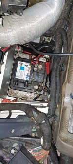
Picture from my installed battery.
I take the battery out at the end of the season.
On the battery is a sticker saying max volts 14.8V.
I don't know what Kind of BMS is in there.
So probably the bms is cutting out at higher voltages than i thought.
I have to check the voltage settings in the charging program of my Junsi 4010Duo Charger, that is the one I do capacity test once a year. I thought it was set to 14.6V.

20241130_102523.jpg
.
 
Last edited:
I'm not sure if there's any kind of active regulation, is there any way I can check? The car is a Maserati Quattroporte S
There's no start/stop system on it but the alternator isn't very accessible as it is right in the middle of the V8, under the intake, so it's not easy to check its reference.
I guess you don't see 10 of these every day ;)
No experiance with Maserati, but on Audi and VW they started showing up on more expensive models in early 2000s, and became more widespread when start/stop became popular maybe 10 years later.
If you have something like that you can have charge voltage from maybe 12,5 to almost 16v. All the systems I have seen have a sensor close to the battery.

I think it would be very tricky to get it to work if you have something like this. Not only because of the voltages, but because of the survaliance of the battery. You are supposed to program if you change battery, even to the same model. I think it wouldn't accept a that diffrent battery.

If you don't have that I think it is rather safe to assume you have a normal alternator with a fixed output voltage.
I think it is always 14,4v on vw and audi, but I think voltages like 14,6v exist.
It is not easy to measure, as you will almost always have some voltage drop in the wiring.
But it might be possible to find specifications for the altarnator or voltage regulator for the alternator for your car.
 
Last edited:
this thread
is about disassembling and examining some marine / starter batteries, and includes info on the BMS of the first one (a "12v" replacement lifepo4 battery). The battery was built several years ago, so things have probably improved, but the company that made the BMS apparently still does....
 
I researched this topic, to much to go into. I am learning so don't want to explain something i'm learning about. One company makes alternators with adjustable regulators but down to only 14v, Op may want to go down to 13.6v. Another option would be to fool the current regulator with a diode. But would not suggest this and have a bad out come.
 
Most commercial 12v LifePo4 batteries are happy to charge from a standard alternator supply, infact some will not reach full charge (14.6v), and have a 50.0 v charge limit voltage.
Obviously your cells are needing a different charge voltage.
I still think a RV supply store sourced DC/DC lithium charge converter is the simplest solution if you select one with a suitable voltage profile.
 
Back
Top