Dual front motor torque steering - Possible to bias motors?

SPACEMAN!

10 µW
Joined
May 5, 2025
Messages
5
Location
Winnipeg
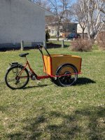
I bought this cargo trike (photo attached) that the previous own converted to into a e-bike. It has two 500w front motors, on the front, with two controllers wired in parallel to drive the motors, but there are a few issues with it I am trying to resolve.

1. Torque steer on throttle - the left hand wheel is mounted backwards to keep the disc brakes and cabling on the inside edge, my understanding of electric motors is that they have less torque in reverse, and as a result the bike steers left under throttle.

2. Battery cut off - this rig should have 2x50A batteries but it only has one (and it's unbranded china battery so the rating is suspect), but as a result going more than half throttle causes the BMS to trip, and the BMS needs its 120v charger to rest. This would be tragic away from home with a load of cargo.

3. Steering at speed is sketchy, this thing doesn't be to scoot hard.

Long term I'd like to get a better battery, and ESC with current/speed limiting, and if there is a dual motor controller that supports speed syncing wheels I'm interested in hearing about solutions, but I suspect I bought a weird setup.

That said, I've spent all my play money and I am looking for a solution I can scratch out of my pile of electronics parts.

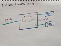
Introducing the biased throttle limiter. I suspect this will work based on my high school electronics background. Using a common 1n4148 diode and two 5K potentiometers I should be able to reduce the throttle signal by 50% and add the the ability to the bias the singal to motor and reduce torque steer.

Is this just crazy enough to work?
 

Attachments

  • photo_2025-05-03_13-11-39.jpg
    photo_2025-05-03_13-11-39.jpg
    496.8 KB · Views: 13
  • photo_2025-05-03_18-17-51.jpg
    photo_2025-05-03_18-17-51.jpg
    163.2 KB · Views: 12
The motors should have exactly the same torque if given the same current, motors have no forward or reverse. Unless the person that built it really had no idea what they were doing and those are geared hub motors with freewheels in which case one of them is literally doing nothing at all.
Interesting. Based on the cable housing I suspect they were not super familiar with bike stuff. I don't see any model information on the hubs, they are brushless (3 phase wire /w hall sensor)

I'll put the trike on some jack stands and test that that theory tonight.
 

Attachments

  • photo_2025-05-05_11-04-02.jpg
    photo_2025-05-05_11-04-02.jpg
    125.7 KB · Views: 4
  • photo_2025-05-03_13-29-15.jpg
    photo_2025-05-03_13-29-15.jpg
    282.6 KB · Views: 4
The motors should have exactly the same torque if given the same current, motors have no forward or reverse. Unless the person that built it really had no idea what they were doing and those are geared hub motors with freewheels in which case one of them is literally doing nothing at all.
And related, if this is the case, is there a way to reverse the freewhell is a geared hub motor?

Edit: answering my own question
 
Last edited:
Those look like direct drive motors. My guess is that you have either weaker power or no power on one side.
 
And related, if this is the case, is there a way to reverse the freewhell is a geared hub motor?

Edit: answering my own question
Yes, you would have to either lock the clutch, or rebuild the motor such that the clutch can be flipped over the other way.

If you can take the gear-mounting shafts out of the clutch and reinstall them so they stick out the ohter side of the clutch instead, then put the gears on them and flip the clutch over and stick it back in the motor, it will now be reversed, so you could then flip the whole motor over and it would run "the same" as a non-flipped motor on the other side of a trike, etc.


If you lock the clutch, then you lose the ability to coast without using motor power that is one of the pluses of a geared hubmotor (not the only one, but the one many people prefer them for). With a locked clutch, there is a lot of drag (probably more than with equivalent DD hubmotor because of gearing ratio), so providing at least a minimal amount of power to the motor to counter the drag is needed to coast. The Grin controllers like Phaserunner have a function to allow this to happen automatically, if you do need it.

It's usually easier to use DD hubmotors for situations where you would have locked the clutch on a geared motor, but it depends on the specific conditions of your riding, usage, terrain, acceleration needed, weight, battery available, etc.

A DD hubmotor will generally take more battery current and motor mass to do the same torque job as a geared hubmotor, so a bigger battery and controller can be needed for that same job with the DD, but it's simpler and has less to fail in it.
 
1. Torque steer on throttle - the left hand wheel is mounted backwards to keep the disc brakes and cabling on the inside edge, my understanding of electric motors is that they have less torque in reverse, and as a result the bike steers left under throttle.

They're only different in reverse if their timing is non-neutral. For brushless motors like hubmotors, they're normally neutrally timed for where the halls are placed, so it's not an issue.

Brushed motors (which those aren't; they appear to be standard "9C clones") may have movable brush holders, which allow you to advance or retard the brush timing vs commutator, and it's common to have advanced timing on brushed motors that are installed in a unidirectional application...like a lawnmower. Others, like drills, have to reverse so they usually use neutral timing.

The torque steer in your case is probably some difference in the way the controllers are configured or wired to the motors. If the phase/hall combination is identical on both, and the reverse wire was used for one side, then the controllers probably have a reverse that uses less power or has some other limitation, which is common but not universal.

To get around that, you can use the learn function (if it has one) to make it spin the motor in reverse *without* the reverse wire being connected, and that will make it the same as the other one.

Or you can manually swap any two but just two phase wires, then swap the hall signal wires around until it runs at lowest current at correct speed with no undue noise in the correct direction.


You could also have two different motor windings. If you don't use the reverse function, and get the wheels off ground, then measure the RPM or wheel speed on each side for max throttle. If it's different on each side despite identical controlelr wiring and settings, the motors are probably differnet windings, which will give different torque and speed for the otherwise identical controller inputs.

A fully configurable controller (FOC type, probably required) on each could let you match them up but it would be much much simpler to just get matched motors.

I use a pair of old used Ultramotors off of A2B Metro bikes for this on my SB Cruiser cargo trike (see link in signature), but I went thru a number of mismatched motor and controller sets over the years before reachign this configuration.


You can adjust the throttle input as you show in hte drawing but it only changes the amount of throttle going to each motor, whcih causes the controller to ask for less speed of each motor for most controllers (except FOC types that normally use torque throttle control), so you will also have a lower top speed on one side as it can never be commanded to go as high as the other.


2. Battery cut off - this rig should have 2x50A batteries but it only has one (and it's unbranded china battery so the rating is suspect), but as a result going more than half throttle causes the BMS to trip, and the BMS needs its 120v charger to rest. This would be tragic away from home with a load of cargo.

The only fixes for this are:
--use the two batteries as required (or other multiple batteries that supply the required power)
--use one bigger better battery capable of handling it
--change the controller settings to reduce current on each to less than half of what the battery can handle *even when it is almost empty*, which will be much less than when it is full, for most batteries.
--physically increase the resistance of the battery-current-monitoring shunt in the controllers. Easiest way is if they have multiple shunts, remove one or more of them, which proportionally reduces current it will then provide. (if there are four, removing one makes it only do 3/4, removing two, 1/2, etc).
--be very careful to monitor voltage drop under load while riding and don't push the throttle beyond whatever causes the lowest voltage just above that.
--disconnect one controller from the battery so it doesn't put any load on it
--disconnect one controller from the throttle so it isn't asked to operate and thus doesn't put any load on the battery


You could also carry a voltage source with you (another battery, for instance) that is as high as the charger output voltage, and connect that to the charge port to reset the BMS, but this just increases the chances of damaging the battery cells from overload / overdischarge by turning the BMS back on when it has shut off to protect them from damage that can lead to a fire.


3. Steering at speed is sketchy, this thing doesn't be to scoot hard.
That's a mechanical issue that would require you to experiment with steering designs, weights, balances, frame designs and lengths and proportions and widths, etc.

Or just never exceed the speed at which it has no problems. ;)

My SBCruiser trike can handle wide left turns at intersections up to maybe 18mph under many conditions, but for tight right turns can be forced down to just above 10mph, less than 15mph max. Partly depends on how it's loaded down, but it isn't made to go faster than 20mph even in a straight line. However, it's still better than most trikes because the weight is lower than anything with a bicycle-type seat (like yours).

If you were to redesign and rebuild your trike so the seat is much lower, your weight will be lower, and it may make tighter turns or the same turns at higher speeds.

But right now I would guess that for your present design, around 10mph, maybe up to 13-15mph, is a likely limit for most turns, and 15mph is a likely "speed limit" even in a straight line because a sudden steering twitch to go around a road problem, etc., could cause a flipover.

Interesting. Based on the cable housing I suspect they were not super familiar with bike stuff.
The cable housing pictured is common standard stuff built into these types of hubmotors.
 
Those look like direct drive motors. My guess is that you have either weaker power or no power on one side.
I put it up jack stands and confirmed that both motors are spinning. The left wheel is observably slower to spin up. I would have been pretty sad if I had a broken motor.

I use a pair of old used Ultramotors off of A2B Metro bikes for this on my SB Cruiser cargo trike (see link in signature), but I went thru a number of mismatched motor and controller sets over the years before reachign this configuration.
Thanks for this detailed post. The SC cruiser looks super cool. I didn't consider that the motors could be mismatched, but that make sense.
The torque steer in your case is probably some difference in the way the controllers are configured or wired to the motors. If the phase/hall combination is identical on both, and the reverse wire was used for one side, then the controllers probably have a reverse that uses less power or has some other limitation, which is common but not universal.

To get around that, you can use the learn function (if it has one) to make it spin the motor in reverse *without* the reverse wire being connected, and that will make it the same as the other one.

Or you can manually swap any two but just two phase wires, then swap the hall signal wires around until it runs at lowest current at correct speed with no undue noise in the correct direction.
This is interesting. I'll check tomorrow and see which method the used to reverse the motor.

You can adjust the throttle input as you show in hte drawing but it only changes the amount of throttle going to each motor, whcih causes the controller to ask for less speed of each motor for most controllers (except FOC types that normally use torque throttle control), so you will also have a lower top speed on one side as it can never be commanded to go as high as the other.
I build my throttle bias circut and tested it out with a 5v hobby motor (I know it's not the same) and I'm going to really test it out tomorrow.

The cable housing pictured is common standard stuff built into these types of hubmotors.
I should have specified cable housing on the brakes and derailleur. The cable housing are missing end cap so they are all frayed, and routed so tight there are little bends in the housing. All easy to replace at the bike coop down the street.
 
1) The motors running at different speeds is obviously not good.
2) Center pivot steering ( also known as wagon steering ) is only valid for slow speed, flat ground use.
Even if the motors operate at the same RPM and at the same torque the steering dynamics will always be a handful.
A road bump to one wheel disrupts the steering and will cause unwanted movements, darting about.
Crowned roads will take over control adding to steering problems, the more weight in the cargo box will require more effort to keep on path.
Best way to salvage the project is power the rear wheel and put regular wheels on front.
 
Last night's troubleshooting session went well.
- I disassembled the brake caliper on the left (slower) wheel and found a fragment of brake cable stuck in the spring retainer for the brake pad that was using the binding.
- The left motor has learned to go the opposite way, reverse wires are not connected

1) The motors running at different speeds is obviously not good.
I borrowed a tachometer from a friend, and after fixing the brake caliper both wheels are spinning at 414 RM +/= 0.5 RPM, and spin up, and coast down much more consistently.

A road bump to one wheel disrupts the steering and will cause unwanted movements, darting about.
Crowned roads will take over control adding to steering problems, the more weight in the cargo box will require more
Yeah, the roads are often crowned here, and back lanes are valleys. So there lots of opportunity for daring around.

That is very fortunate! :bigthumb:
Apparently they don't open till July :( So I went down do my local bike shop and got a bunch of cables, a few meters of each housing, and all the other bits.


Todo:
- Test using the low speed mode on the controller (414 RPM is ~50 km on a 26" wheel, too damn fast anyways)
- Install new cables and housing
- rebuild bottom bracket
- more (any) build it lights!
 
Last edited:
Best way to salvage the project is power the rear wheel and put regular wheels on front.

Can you gain enough from selling the two motors to substitute a single motor for the rear wheel?
 
Last night's troubleshooting session went well.
- I disassembled the brake caliper on the left (slower) wheel and found a fragment of brake cable stuck in the spring retainer for the brake pad that was using the binding.
- The left motor has learned to go the opposite way, reverse wires are not connected


I borrowed a tachometer from a friend, and after fixing the brake caliper both wheels are spinning at 414 RM +/= 0.5 RPM, and spin up, and coast down much more consistently.


Yeah, the roads are often crowned here, and back lanes are valleys. So there lots of opportunity for daring around.


Apparently they don't open till July :( So I went down do my local bike shop and got a bunch of cables, a few meters of each housing, and all the other bits.


Todo:
- Test using the low speed mode on the controller (414 RPM is ~50 km on a 26" wheel, too damn fast anyways)
- Install new cables and housing
- rebuild bottom bracket
- more (any) build it lights!
Good progress (y)
 
Back
Top