Alan B
100 GW
News - The V1.0 board is openly available, see the V1.0 page linked at the end of this posting
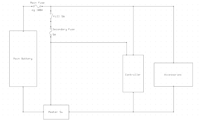
Ebike designs have a variety of ways of handling the "master power switch" covering a range from just using plugs to contactors and electronic switches. On my current Greyborg I used a "Kill" switch that feeds power to the controller and lights while the real master switch is some large PowerPole connectors. I find that the Kill switch is a really nice way to turn the bike on and off, much more convenient than getting to and fighting with the big connectors and precharge resistors or watching your connectors get eaten away by arc-flashes at each hookup.
The downside to this technique is that the bike is still somewhat "on" all the time and the controller is draining the battery slowly even though the logic power is off as the high power section is always energized. Installing a big contactor is not that appealing, but making a small one with FETs is an interesting possibility. A few folks on ES have done similar things, and many BMS systems have an FET switch built into them. In fact this master switch could be used as part of a DIY BMS as well as being the master switch.
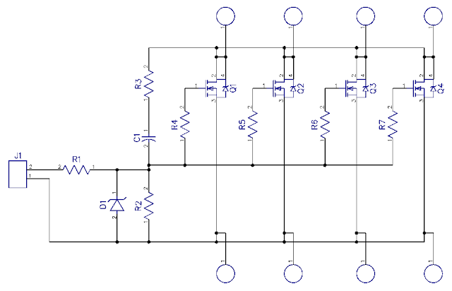
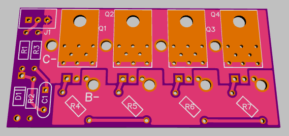
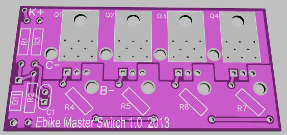
Lately I've been learning a (new to me) PC layout package called DipTrace, so I decided to make a layout for a simple electronic Master Switch. This one has a feedback type soft start and four parallel FETs which should be adequate for a 24 FET controller. If you push your controller hard you might need a heatsink and beefed up traces. Or we could add a couple more FETs easily enough
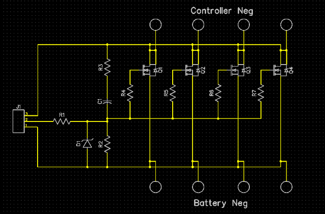
This design uses four parallel 12 gauge wires to carry the current (equivalent to a six gauge wire!), and to turn it on a single wire to the Kill (or ignition) switch connects to +battery. The current carrying portion of the switch connects between Battery minus and Controller minus. So only three connections. It will draw only about a milliamp when on (to power itself), and when off only the leakage of the big FETs which is typically in the microamps region depending on temperature and FET quality.
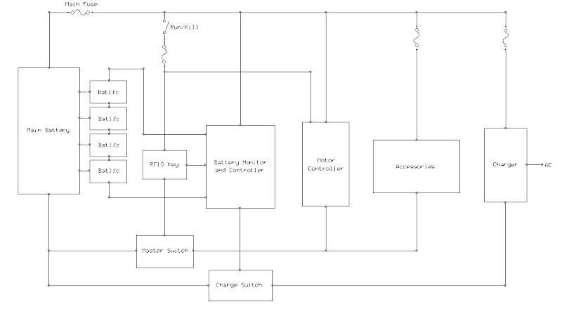
If you want to add a keyswitch or hidden switch in addition or in lieu of a Kill switch (though all ebikes should have a standard kill switch) you can add any switches in series and feed this Master Switch board. Later I'll make an RFID ignition switch that will use this board to control the main power (together with the Kill switch).
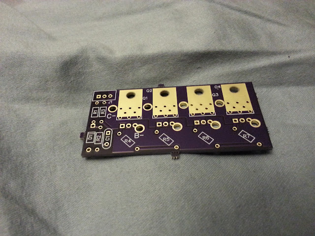
This is an easy to build PC board with all through-hole parts. The FETs are bolted to the PC board to make a solid mechanical unit so vibration won't break the leads. If it is of interest to other folks we might be able to make extra boards.
Updates, index here:
V1.0 board info post: http://endless-sphere.com/forums/viewtopic.php?f=14&t=54225&p=808093#p808093 This board is available at OSH Park, there is a link in the page to order them.
V1.1 board info post: http://endless-sphere.com/forums/viewtopic.php?f=14&t=54225&p=825100#p825100
Ebike designs have a variety of ways of handling the "master power switch" covering a range from just using plugs to contactors and electronic switches. On my current Greyborg I used a "Kill" switch that feeds power to the controller and lights while the real master switch is some large PowerPole connectors. I find that the Kill switch is a really nice way to turn the bike on and off, much more convenient than getting to and fighting with the big connectors and precharge resistors or watching your connectors get eaten away by arc-flashes at each hookup.
The downside to this technique is that the bike is still somewhat "on" all the time and the controller is draining the battery slowly even though the logic power is off as the high power section is always energized. Installing a big contactor is not that appealing, but making a small one with FETs is an interesting possibility. A few folks on ES have done similar things, and many BMS systems have an FET switch built into them. In fact this master switch could be used as part of a DIY BMS as well as being the master switch.
Lately I've been learning a (new to me) PC layout package called DipTrace, so I decided to make a layout for a simple electronic Master Switch. This one has a feedback type soft start and four parallel FETs which should be adequate for a 24 FET controller. If you push your controller hard you might need a heatsink and beefed up traces. Or we could add a couple more FETs easily enough

This design uses four parallel 12 gauge wires to carry the current (equivalent to a six gauge wire!), and to turn it on a single wire to the Kill (or ignition) switch connects to +battery. The current carrying portion of the switch connects between Battery minus and Controller minus. So only three connections. It will draw only about a milliamp when on (to power itself), and when off only the leakage of the big FETs which is typically in the microamps region depending on temperature and FET quality.
If you want to add a keyswitch or hidden switch in addition or in lieu of a Kill switch (though all ebikes should have a standard kill switch) you can add any switches in series and feed this Master Switch board. Later I'll make an RFID ignition switch that will use this board to control the main power (together with the Kill switch).
This is an easy to build PC board with all through-hole parts. The FETs are bolted to the PC board to make a solid mechanical unit so vibration won't break the leads. If it is of interest to other folks we might be able to make extra boards.
Updates, index here:
V1.0 board info post: http://endless-sphere.com/forums/viewtopic.php?f=14&t=54225&p=808093#p808093 This board is available at OSH Park, there is a link in the page to order them.
V1.1 board info post: http://endless-sphere.com/forums/viewtopic.php?f=14&t=54225&p=825100#p825100


