Ebike shuts down with voltage error code at 500W

Joined
Jun 30, 2024
Messages
14
Location
86326
After many posts referring me back to the battery, I've decided to do the arduous task of ripping apart the pack and figure out where I went wrong. My bms wont display cell data all of a sudden so I hope I didn't fry it. I apologize for any spelling errors. I had eye surgery today and can barely read what I'm writing. Thanks for all the help. Ill post back when I figure out what went wrong

have searched for an answer here and elsewhere but none of the answers seemed to apply so here goes the same old question hoping for a fresher answer since 2015

I have a crappy Chinese bike which I bought from Amazon. The Hall wires came straight out the axle and we're pulled so tight that a couple broke. After ripping it apart, extending the wires a painfully putting it back together, some more broke. I bought a new 1000w motor on Ali baba.

I figured while I was at it I'd build a 14s5p battery from EVE 3200mAh 18650s (10 A max draw, 5A constant) (IR on 5 cell parallel range 67m ohms to 127m ohms)with a 100balance bms and active 1A balancer with Bluetooth. and a new controller with a "900W" display (controller 40A 36v to72v). Installed the rear hub motor and new spokes. Found out my throttle was bad from error msg on display. Replaced that. Aligned brake rotors and pads Set controller up for max 20A and 48v. Set wheel size, no speed control, 42v battery cutoff, and appropriate (I think) pedal assist settings

All connections seem secure and the cells in the battery were balanced to 3.7v prior to install then the balancer rebalanced them at 4.15v (I set that as max and min at 3.1v on bms and controller) I rewired everything with 22awg wire for low voltage and 12AWG wire for high voltage. Connections twisted, soldered, heat shrink with glued heat shrink.

Now at 500w in anything over PAS2 I get a brief low voltage error code then it shuts down. I set the amp draw on controller to a max of 10A thinking max 580W (58v 10A) on a 1000w motor should be no problem. No help. All cells in p configuration are balanced to within 0.01v and at 10A draw I can't imagine it's drawing anywhere near even 1C much less the 3C they are rated at max . There is a setting asking which magnet it should base the speed at. I didn't think that was it since I set the speed limiter off. Also a setting asking "assisted magnetic steel disc type " but I tried all 3 types and no difference.

Anyone have any idea what is going on?
 
Last edited:
strange, do you have a readout of the numerical voltage? that would be helpful to see if the voltage is really low or not.

If it is, we can trace the problem to the battery / BMS

This would be a cheap way to get one:
Turnigy 180A Watt Meter and Power Analyzer
 
I have a Bluetooth readout from the bms. They are all within 0.01v and it fully charged at 4.15v~ and after my riding a little bit and testing they are all at 4.05v~ (~ signifying within 0.01v) I'll have to get a screenshot tomorrow because it quits balancing and shuts down at 1 hour. On full charge it was at 58.2v
 
Can the bluetooth read out tell you the voltage in real time, IE while you are putting maximum load on it?
It would be helpful to know if the voltage is actually dropping or your controller is acting up.
 
Now at 500w in anything over PAS2 I get a brief low voltage error code then it shuts down.
If the system actually powers off (display turns off) then your battery's BMS is turning the output off to protect the cells against overcurrent and/or low-voltage. That usually means the cells are incapable of handling the current draw and are dropping below BMS LVC.

If the system isn't powering off but is just shutting off the assist, then that usually means the controller's LVC has been reached due to either a less extreme version of the above cell issue, or a connection in the main battery + / - wiring between cells and controller board that has too high a resistance and is causing significant voltage drop across it under load.
 
it quits balancing and shuts down at 1 hour.
does this mean the BMS turns the pack charging input off after 1 hour of charging, but the BMS remains active and it's output is still on, and you are still connected to the BMS via BT? That would probably be normal behavior, assuming it only takes 1 hour of balancing and charging after usage.

Or does this mean the BMS entirely shuts down, BT, input, and output, after 1 hour? This would probably not be normal behavior, unless there is some BMS setting for a timer to do this. It could be from a number of different problems.
 
There is a setting asking which magnet it should base the speed at.
That kind of setting usually means whether it should use the separate wheel speed sensor line, or the motor hall sensor line.

The former is usually either a single pole or a six pole sensor if it's inside the motor with it's own separate speed wire, or a single pole if it's an external sensor with a magnet mounted to a wheel spoke.

The latter is either the same number of poles as half the number of magnets in a DD hubmotor, or that number times the gear ratio for a geared hubmotor.
 
IR on 5 cell parallel range 67m ohms to 127m ohms
That is pretty awful, if the cells are so badly mismatched that you have some groups with twice the resistance (and thus twice the voltage sag, and possibly half the capacity) as other groups.

I'd return all those cells and get new matched cells that all have the *same* properties, as identical as possible.

Remember that any disparity between them will only grow worse with use and age.
I used 2 different chargers to charge and discharge the parallel cells and, maybe a coincidence, one charger recorded all higher resistance and the other all the lower resistance. I didn't worry about it because 127 was the worst and it didn't seem so bad to me.
 
That's 67-127 milliohms for the whole 5P combo, not each cell by itself? That would be 1-2 ohms of series resistance in a 14S. Means that 10 amps would sag 10-20 volts, I guess that would trip a BMS,

Brand new Eve 33C's are under 20 millilohms per cell for series resistance. A 5P group would be under 4 milliohms.
 
I googled these cells and see that the IR should be under 30mOhm.

127mOhm is way out of spec and either indicates massive wear, or the cell is counterfeit.
I take it that you didn't do capacity tests on these batteries or match them before assembling the pack?
Did you get them incredibly cheap?
 
If the system actually powers off (display turns off) then your battery's BMS is turning the output off to protect the cells against overcurrent and/or low-voltag
I googled these cells and see that the IR should be under 30mOhm.

127mOhm is way out of spec and either indicates massive wear, or the cell is counterfeit.
I take it that you didn't do capacity tests on these batteries or match them before assembling the pack?
Did you get them incredibly cheap?

e. That usually means the cells are incapable of handling the current draw and are dropping below BMS LVC.
I googled these cells and see that the IR should be under 30mOhm.

127mOhm is way out of spec and either indicates massive wear, or the cell is counterfeit.
I take it that you didn't do capacity tests on these batteries or match them before assembling the pack?
Did you get them incredibly cheap?
i did do a capacity check on the 14 P strings and they all came out between 15450 and 15700. I've checked around and found there are fakes out there that only go to 3100mAh and figured it was either that or the fact that I charge and discharge from only 3.1v and 4.15v instead of the data sheet which says 2.8v to 4.2 v. Either way, I'm going to have to tear down this pack and find a way to put these cells under some stress during drain.Yes I got them cheap. About $1.20 per cell. You get what you pay for.

If the system isn't powering off but is just shutting off the assist, then that usually means the controller's LVC has been reached due to either a less extreme version of the above cell issue, or a connection in the main battery + / - wiring between cells and controller board that has too high a resistance and is causing significant voltage drop across it under load.
It's starting to sound like I have a loose connection or weak set of cells in the battery. None of my testing was available current draw so that may be it. I dread taking it apart again. I checked every connection before wrapping the cells and then the pack. They all seemed to discharge at the same rate and current
 
If the system actually powers off (display turns off) then your battery's BMS is turning the output off to protect the cells against overcurrent and/or low-voltage. That usually means the cells are incapable of handling the current draw and are dropping below BMS LVC.

If the system isn't powering off but is just shutting off the assist, then that usually means the controller's LVC has been reached due to either a less extreme version of the above cell issue, or a connection in the main battery + / - wiring between cells and controller board that has too high a resistance and is causing significant voltage drop across it under load.
Would adding a 30A 50v diode on each parallel string help this? I can't find a 30A 4v diode. Maybe the whole series of 14s5p needs this as I won't be exceeding 30A? Don't know a lot about diodes
 
That's 67-127 milliohms for the whole 5P combo, not each cell by itself? That would be 1-2 ohms of series resistance in a 14S. Means that 10 amps would sag 10-20 volts, I guess that would trip a BMS,

Brand new Eve 33C's are under 20 millilohms per cell for series resistance. A 5P group would be under 4 milliohms.
Would adding a 30A 50v diode help this? I won't be using more than 30A. If so, should it be on each 5P parallel string or the entire 14s pack? I don't know much about diodes
 
Can the bluetooth read out tell you the voltage in real time, IE while you are putting maximum load on it?
It would be helpful to know if the voltage is actually dropping or your controller is acting up.
 

Attachments

  • Screenshot_20241231_132308_Balance BMS.jpg
    Screenshot_20241231_132308_Balance BMS.jpg
    284.2 KB · Views: 4
  • Screenshot_20241231_132319_Balance BMS.jpg
    Screenshot_20241231_132319_Balance BMS.jpg
    288.8 KB · Views: 4
  • Screenshot_20241231_132331_Balance BMS.jpg
    Screenshot_20241231_132331_Balance BMS.jpg
    284 KB · Views: 4
  • Screenshot_20241231_132341_Balance BMS.jpg
    Screenshot_20241231_132341_Balance BMS.jpg
    287.1 KB · Views: 4
  • Screenshot_20241231_132355_Balance BMS.jpg
    Screenshot_20241231_132355_Balance BMS.jpg
    287.1 KB · Views: 4
  • Screenshot_20241231_132412_Balance BMS.jpg
    Screenshot_20241231_132412_Balance BMS.jpg
    284.9 KB · Views: 4
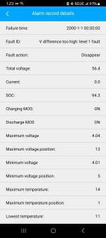
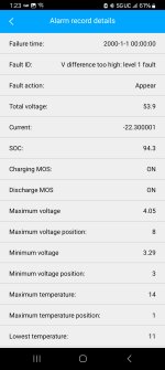
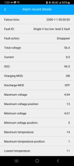
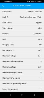
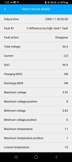
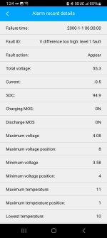
Could be wrong in understanding it, but screen shot two says the battery was at 54V, pulling 22 amps. and bank 8 was at 4.01 volt while bank 3 sagged to 3.29V. Is that right?

To me, that would suggest bad spot welds on bank 3. Are you a good builder and your batteries normally welded nice? It's 5P, and maybe two or three cells in that 5P had welds that lifted off. Or if you trust your craftmanship, then the cells are bad,

Oh well. Happy New Year. Off to the celebrations.


.
 
A bunch of your cells are going too low during discharge.
Two possibilities:

A) Your interconnects aren't good, or connection to the BMS
B) The pack is not well matched, and variances in cells are large

For case B, you need to disassemble this pack, cycle test, note IR for each cell and match.
During this process you will probably notice a huge variance in these cells. If so, you were sold some mixture of second life ( recycled ) cells.
 
Last edited:
Would adding a 30A 50v diode help this? I won't be using more than 30A. If so, should it be on each 5P parallel string or the entire 14s pack? I don't know much about diodes
Diodes just block current from flowing in one direction, only allowing it in the other.

If you need to limit current you do that at the controller, by programming it's current limit, or buying a controller with a nonprogrammable limit at the level you want.

In the case of cells that aren't handling even 10A properly, you'd need to limit to less than 10A, to however low is required to keep the cells from sagging in voltage significantly. That may mean that your system would then not be able to do the job you need it to, in which case the replacement of the battery with one that does do what you need it to would be required. (or repair of the one you have, if the problems it has are not caused by the cells themselves--if they are you have to replace those to fix it, and that is extensive enough work to make it easier to replace the whole battery.
So since you seem to understand this issue in detail, I have another question. My cells individually read around 87 Milliohms on average of 15 of them so far. I connected 5 parallel cells with spot welder and the spot welds aren't professional but withstand reasonable pulling force. (Maybe as if you were opening a really excellent refrigerator door? A little more than that). I'm using 0.10x8mm pure nickel roll. To connect every + to every + and every- to every-. All voltages are within 0.01v and all capacities are within 2% (3100mAh to 3160mAh for example).
Why is my end IR measuring ABOVE 100Miliohms
 
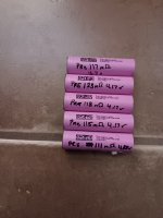
So, knowing resistance drops over parallel strings, and with the following photos. Would someone please explain how I get the opposite effect? I'm building a temporary battery for my bike so I can still use it while I rebuild the other one. These are used cells but every one has been through 2 charge/discharge cycles and amazingly all came out between 2750 and 2830 mAh. They are only rated at 2600 so....?
Photos:
1 IR and voltage of 5 cells
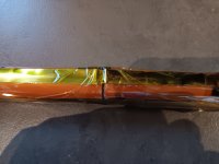
2 Welds 99.6% nickel strip. No spark when cutting with disc
3 First wrap ( second is a pvc shrink for each parallel string but until I understand why the IR is high I'll wait for that)
4 Final IR
 

Attachments

  • 20250102_155654.jpg
    20250102_155654.jpg
    1.4 MB · Views: 6
  • 20250102_163548.jpg
    20250102_163548.jpg
    2.8 MB · Views: 5
  • 20250102_164035.jpg
    20250102_164035.jpg
    1.3 MB · Views: 5
  • 20250102_165300.jpg
    20250102_165300.jpg
    1.5 MB · Views: 5
  • 20250102_165327.jpg
    20250102_165327.jpg
    2.6 MB · Views: 5
  • 20250102_165722.jpg
    20250102_165722.jpg
    3.2 MB · Views: 6
Last edited:
amazingly all came out between 2750 and 2830 mAh. They are only rated at 2600 so....?

Sure, and a car model in a given year is rated at XX horespower. Do you think every single example of that car built will have exactly that horsepower under all temperature conditions and with all fuels at all times? To how many decimal places?

It's a nominal rating. 'Nominal' effectively means 'named'. It's named as a 2600 mAh cell as they aimed to fulfill that when they designed it, and if they did their job right, all of them will be at least that when brand new in general usage. But not too much more, as that costs the manufacturer needlessly.

Cells lose capacity over time and usage. A rip-off manufacturer will notice the cells are coming off the line at 2750+ and charge extra for them even though the cells will only manage that once in their entire lifetime. A quality manufacturer will be happy that the cell will perform as advertised for the first year so they can keep their quality reputation.
 
So since you seem to understand this issue in detail, I have another question. My cells individually read around 87 Milliohms on average of 15 of them so far. I connected 5 parallel cells with spot welder and the spot welds aren't professional but withstand reasonable pulling force. (Maybe as if you were opening a really excellent refrigerator door? A little more than that). I'm using 0.10x8mm pure nickel roll. To connect every + to every + and every- to every-. All voltages are within 0.01v and all capacities are within 2% (3100mAh to 3160mAh for example).
Why is my end IR measuring ABOVE 100Miliohms
Best guess is the testing device isn't correctly doing the tests, or the testing method itself doesn't match the device's requirements.

Resistance should drop with paralleled resistances.

The other possibility is that something has damaged the cells during assembly, but that is more typical of soldered packs than welded ones.
 
Back
Top